System and method for managing the buoyancy of an underwater vehicle

a technology of underwater vehicles and buoyancy, applied in the field of mechanical arts and methods, can solve the problems of inefficiency, time-consuming trips to the surface, and sg greater than unity, and achieve the effects of reducing the cost of diving

Active Publication Date: 2007-05-08
SIMPSON STEVEN M
View PDF2 Cites 41 Cited by
  • Summary
  • Abstract
  • Description
  • Claims
  • Application Information

AI Technical Summary

Problems solved by technology

Supporting payloads with a specific gravity (SG) greater than unity tends to make the ROV sink.
Replacing liquid with gas in the ballast tank makes the ROV rise while replacing gas with liquid tends to make the ROV sink.
Such trips to the surface consume time and are inefficient, regardless of how the ROV is deployed.

Method used


Image

  • System and method for managing the buoyancy of an underwater vehicle
  • System and method for managing the buoyancy of an underwater vehicle
  • System and method for managing the buoyancy of an underwater vehicle

Examples


Embodiment Construction

Introduction

[0026]The present invention provides time saving work methods and systems applicable to the operation of a ROV. ROV systems operated according to the present invention have specific features and advantages, including, but not limited to, increased productivity and reduced operating risk. These features and advantages are especially evident when the ROV is repetitively moving payloads from one location to another.

[0027]As noted above, a ROV may advantageously employ the present invention to support or to carry out underwater work, including maintenance, repair, and construction work. The system and methods described enable a ROV to replenish its gas supply proximate to the worksite. These and other features and advantages of the present invention will now be described in detail with reference to the accompanying drawings.

Improved ROV Work Methods

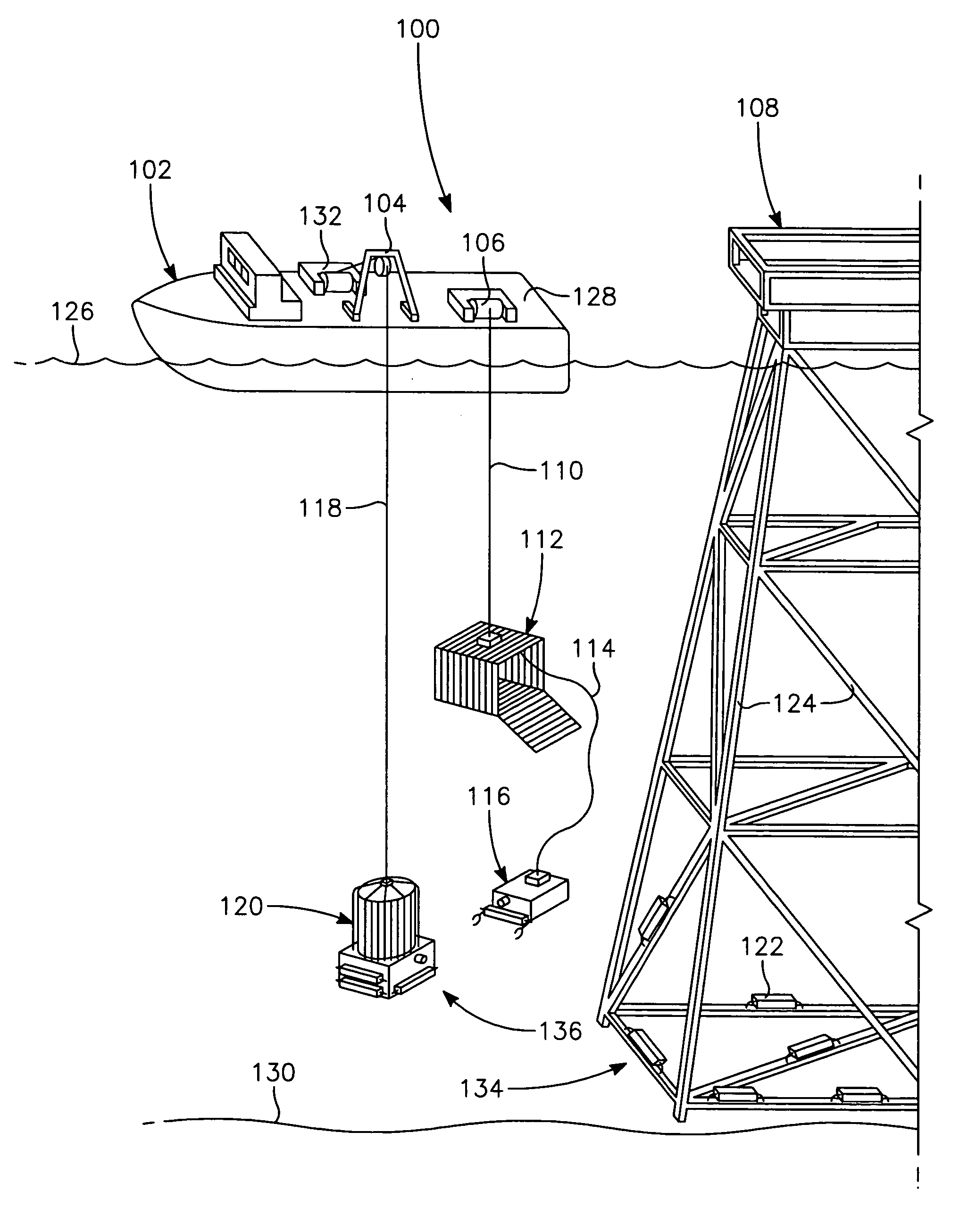
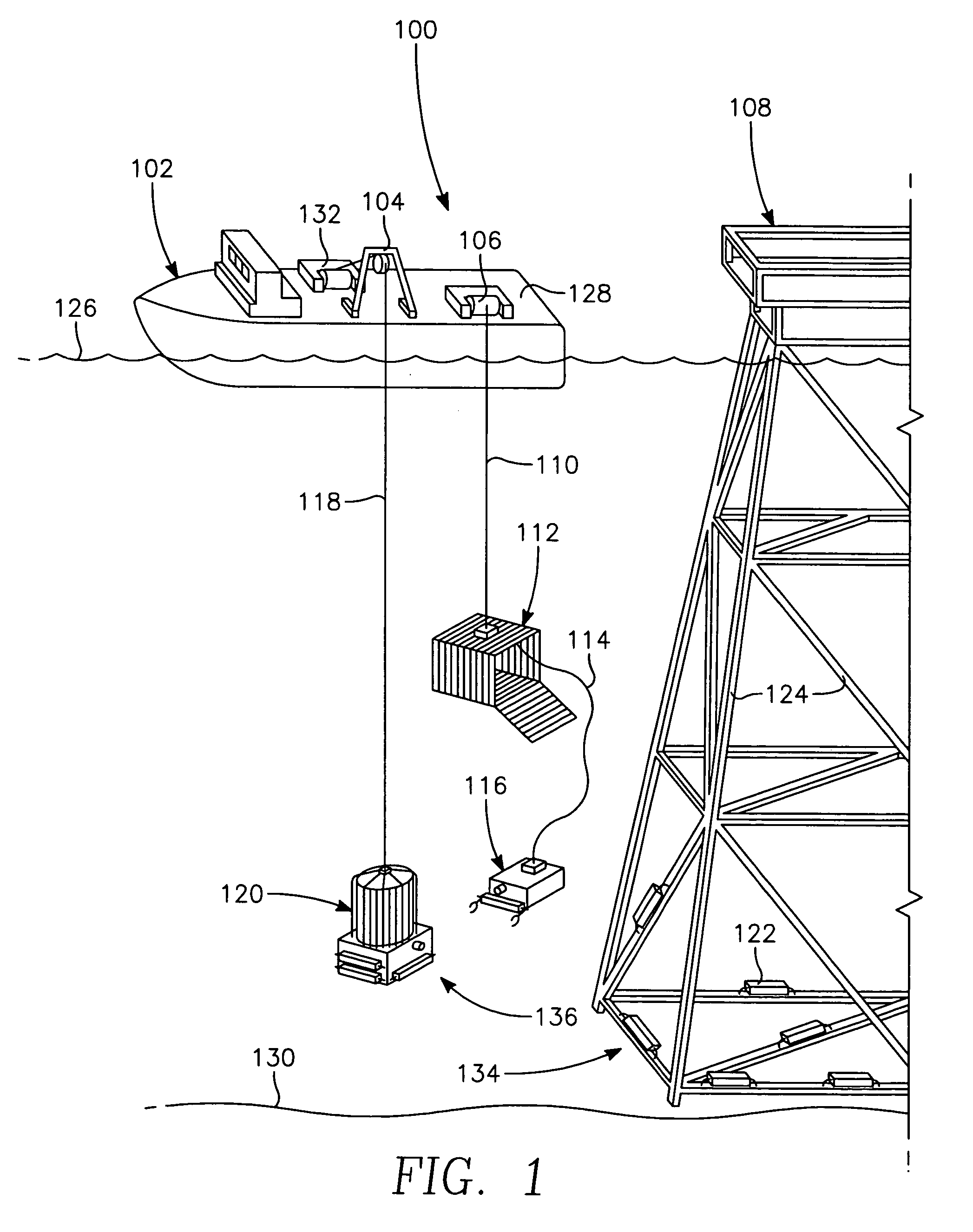
[0028]In an embodiment, FIG. 1 shows a ROV spread 100 with a deployed ROV 116 mobilized at an underwater worksite 130. The works...


PUM


Abstract

The present invention provides a system and a method, including a gas supply proximate to a worksite, for repetitively recharging the ballast tank of an underwater vehicle as required to control its buoyancy while moving underwater payloads.

Description

BACKGROUND OF THE INVENTION[0001]1. Field of the Invention[0002]The present invention relates to the mechanical arts and methods that embody underwater work methods. More particularly, it relates to devices and methods for improving the productivity of a remotely operated vehicle (ROV) engaged in underwater maintenance and construction work.[0003]2. Description of Related Art[0004]Conventional underwater work techniques often include the use of remotely operated vehicles (ROV's). A surface support vessel and its associated personnel support and operate the ROV. The ROV may be deployed directly from the support vessel or from the surface via a tether management system (cage). When deployed directly from the surface, the ROV is connected to its control and powering components on the support vessel with an umbilical cable. When deployed from the surface in a cage, the cage and ROV are lowered to a location near the worksite on a similar umbilical cable. Thereafter, the ROV may be maneu...

Claims


Application Information

Patent Timeline
Patent Type & Authority Patents(United States)
IPC IPC(8): B63G8/14B63G8/22
CPCB63C11/42B63G8/22
Inventor SIMPSON, STEVEN M.
Owner SIMPSON STEVEN M
Why Eureka
Try Eureka