Shock absorber for a remote-controlled model car

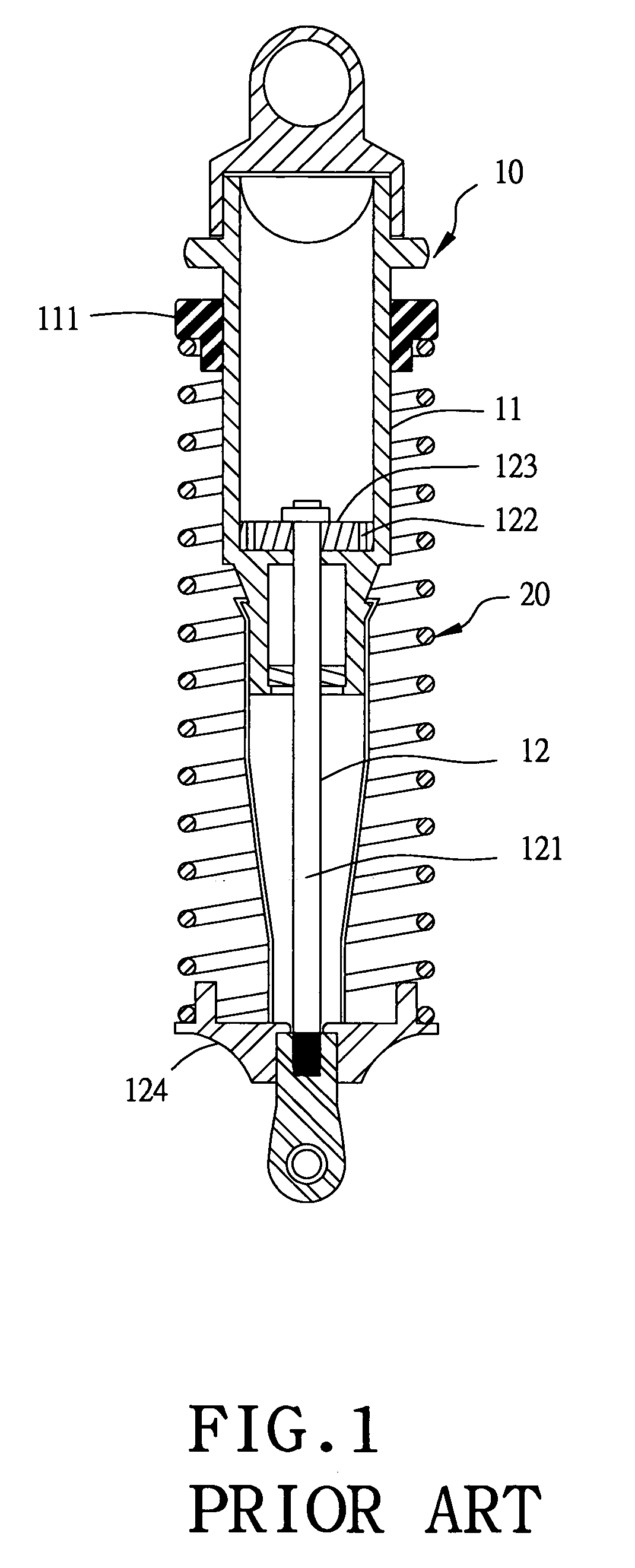
a remote-controlled model car and shock absorber technology, applied in the direction of shock absorbers, dampers-spring combinations, vibration dampers, etc., can solve the problems of conventional shock absorbers that cannot automatically adjust their buffering force, conventional shock absorbers cannot produce a marked shock absorber effect,

Inactive Publication Date: 2007-05-08
GOLDEN LION ENTERPRISE
View PDF11 Cites 7 Cited by
  • Summary
  • Abstract
  • Description
  • Claims
  • Application Information

AI Technical Summary

Benefits of technology

[0006]The objective of the invention is to offer a shock absorber for a remote-controlled model car shock, which has a sealing member fixed on the upper outer side of the piston of a piston rod. The sealing member has its opposite sides respectively formed with a flexible portion aligned to the flow-guiding hole of the piston, with a flow gap formed between the flexible portion of the sealing member and the upper outer side of the piston. The flow gap, matching with the extent of an external force imposed upon the shock absorber, can be properly diminished or closed up. The two flexible portions of the sealing member are respectively bored with a flow-adjusting hole smaller than and aligned to the flow-guiding hole of the piston for reducing the flow amount of liquid oil flowing toward the flow-guiding hole. When pressed by external force of different extents, the shock absorber can automatically adjust its buffering force to a most appropriate condition by adjustment of the position of the flow-adjusting holes and the size of the flow gaps.

Problems solved by technology

However, the flow-guiding holes 122 of the piston 123 of a conventional shock absorber are fixed in size; therefore, the buffering force produced by the conventional shock absorber cannot be altered.
In other words, the conventional shock absorber cannot automatically adjust its buffering force to a most appropriate condition in accordance with the condition of an uneven road or the extent of swaying.
As a result, the shock absorber fails to produce a marked shock absorbing effect, or the buffering force produced is insufficient, likely to let the remote-controlled model car jump and sway up and down violently or collide with the ground and get damaged.

Method used


Image

  • Shock absorber for a remote-controlled model car
  • Shock absorber for a remote-controlled model car
  • Shock absorber for a remote-controlled model car

Examples


Embodiment Construction

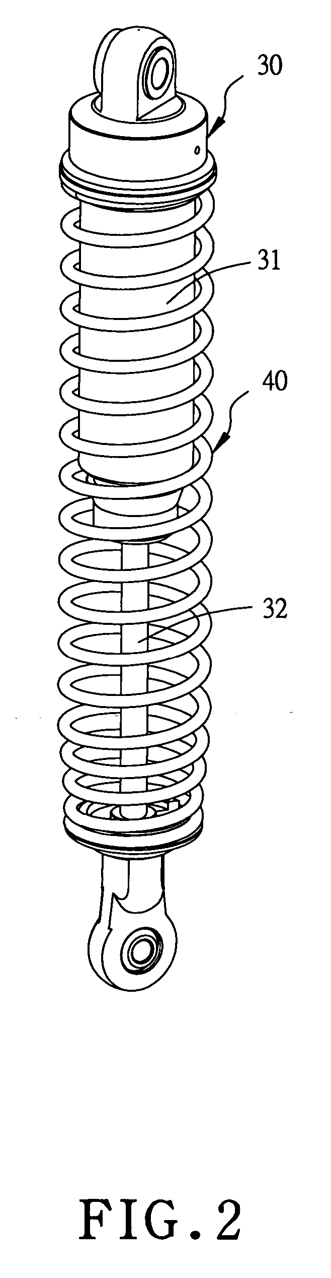
[0017]A preferred embodiment of a shock absorber for a remote-controlled model car in the present invention, as shown in FIGS. 2, 3 and 4, includes a hydraulic cylinder 30 and a spring member 40 as main components combined together.

[0018]The hydraulic cylinder 30 consists of a cylinder 31 and a piston rod 32 that has the upper end of its rod body 321 connected with a piston 323 with two flow-guiding holes 322.

[0019]The spring member 40 is positioned between the cylinder 31 and the piston rod 32.

[0020]The piston 323 is bored with two symmetrical positioning holes 324 at proper locations of the opposite upper sides.

[0021]A sealing member 33 shaped as an elongate strip, as shown in FIG. 5, has its intermediate portion formed with a circular portion 331 bored with an insert hole 332 in the center to be fitted on the upper end of the rod body 321 of the piston rod 32. The circular portion 331 of the sealing member 33 is locked in position by a nut 326 screwed with a bolt portion 325 at t...


PUM


Abstract

A shock absorber for a remote-controlled model car includes a sealing member fixed on the topside of a piston. The sealing member has two opposite flexible portions respectively matching with the flow-guiding holes of the piston, with flow gaps formed between the flexible portions and the upper outer sides of the piston. The flow gap, matching with the extent of an external force imposed upon the shock absorber, can be properly diminished or closed up. Each flexible portion is bored with a flow-adjusting hole smaller than and aligned to the flow-guiding hole of the piston for reducing the flow amount of liquid oil flowing through the flow-guiding hole. When pressed by different-extent external forces, the shock absorber can automatically adjust its buffering force to an excellent condition by adjustment of the flow-adjusting holes and the flow gaps.

Description

BACKGROUND OF THE INVENTION[0001]1. Field of the Invention[0002]This invention relates to a shock absorber for a remote-controlled model car, particularly to one able to automatically adjust its buffering force to an excellent condition for matching with different-extent external forces, having an excellent effect in buffering and shock absorption.[0003]2. Description of the Prior Art[0004]A conventional shock absorber for a remote-controlled model car includes a hydraulic cylinder 10 and a spring member 20. The hydraulic cylinder 10 consists of a cylinder 11 and a piston rod 12. The cylinder 11 has its interior filled with liquid oil and the rod body 121 of the piston rod 12 has its upper end connected with a piston 123 with two flow-guiding holes 122 to be clogged in the interior of the cylinder 11. The spring member 20 is positioned between the upper spring holder 111 of the cylinder 11 and the lower spring holder 124 at the lower end of the piston rod 12. Thus, when the remote-c...

Claims


Application Information

Patent Timeline
Patent Type & Authority Patents(United States)
IPC IPC(8): F16F9/50
CPCF16F9/3228F16F9/3484F16F9/3485
Inventor CHANG, LIEN-SHENG
Owner GOLDEN LION ENTERPRISE
Why Eureka
Try Eureka