Lift unit for vertical take-off and landing aerial vehicle

Inactive Publication Date: 2007-05-08
MCKINNEY CHARLES CECIL
View PDF7 Cites 3 Cited by
  • Summary
  • Abstract
  • Description
  • Claims
  • Application Information

AI Technical Summary

Problems solved by technology

The helicopter requires, comparatively, a large amount of power, because of the aerodynamic drag on the rotor, leading to inefficiencies.
The helicopter is also mechanically complex, requiring swash plates, push rods, and anti-torque measures.
Another major drawback is that the forward velocity of the vehicle, as a whole, is limited because of the additive speeds of the vehicle and the forwardly advancing blade approaching mach one, disrupting and unbalancing lift.
The helicopter also generates a great amount of downward efflux.
The vectored thrust machine has the same problem of excessive downward efflux, since it is dependent upon the action/reaction principle.
The tilt-wing aircraft is complex, mechanically, requiring an engine of a weight and class able to produce eno

Method used


Image

  • Lift unit for vertical take-off and landing aerial vehicle
  • Lift unit for vertical take-off and landing aerial vehicle
  • Lift unit for vertical take-off and landing aerial vehicle

Examples


Embodiment Construction

—PREFERRED EMBODIMENT

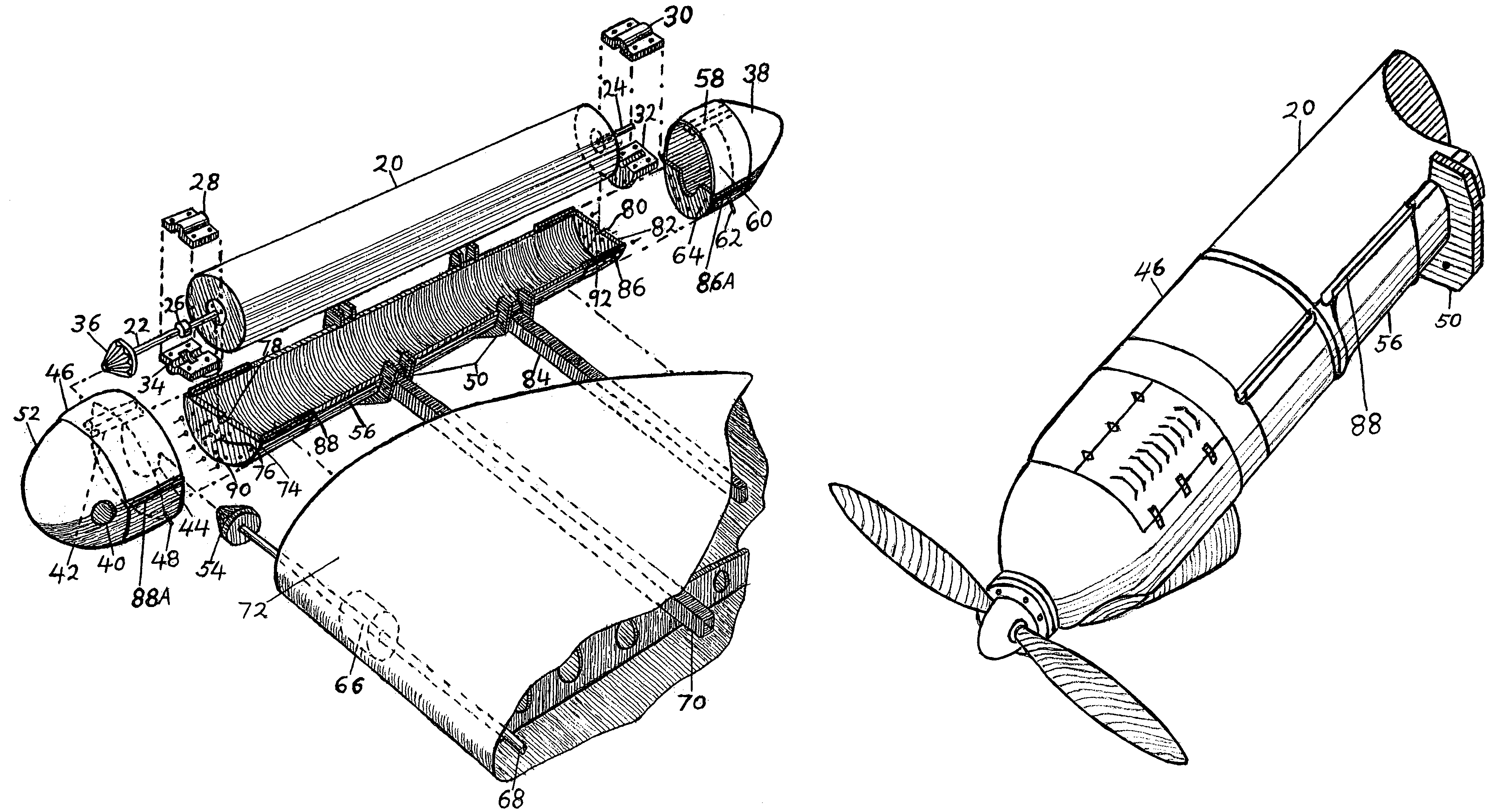
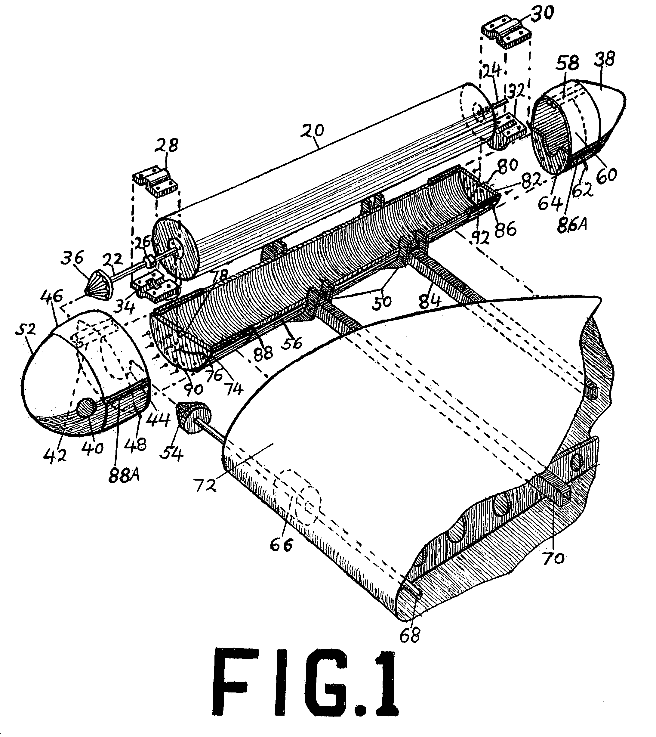
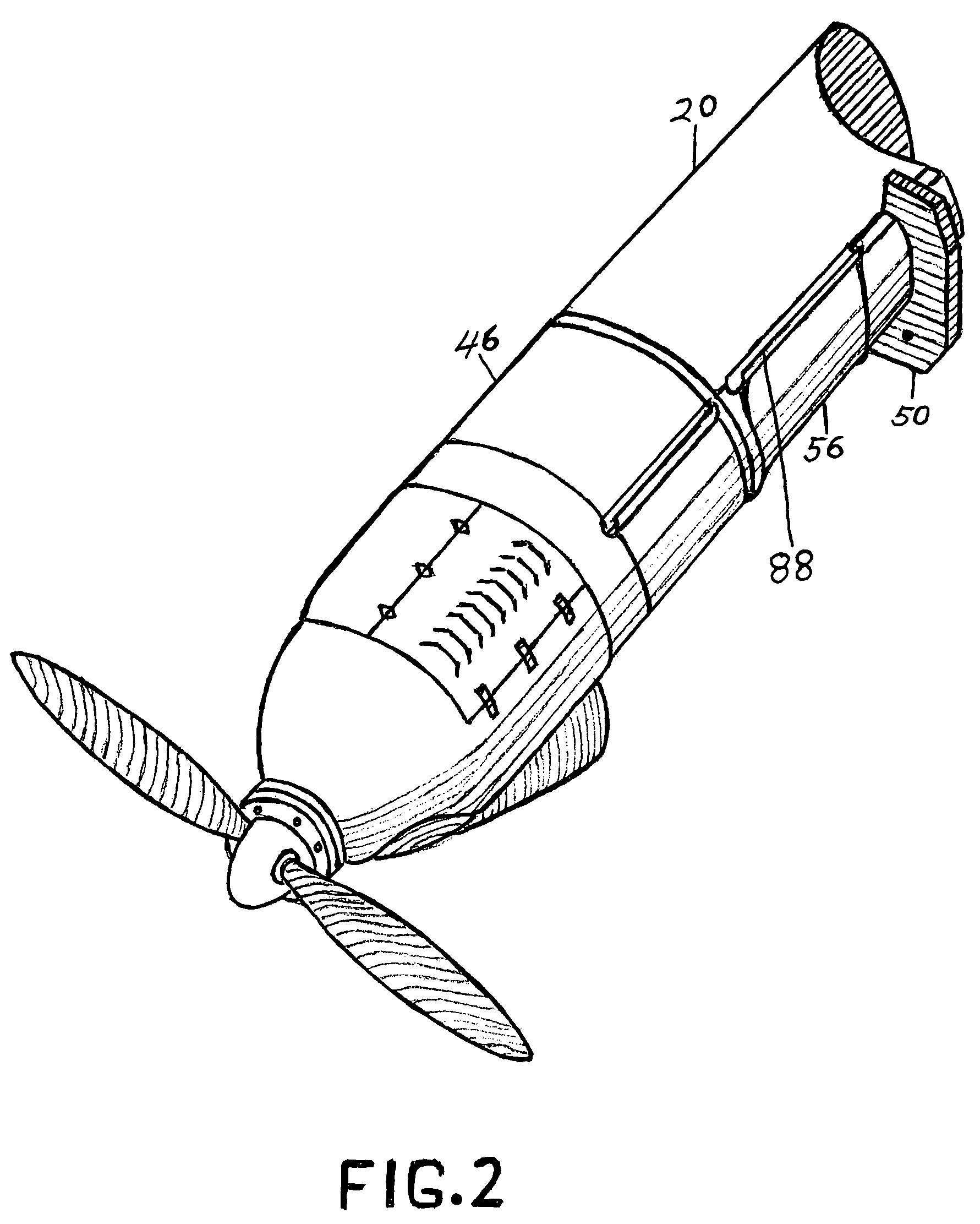
[0041]The structure of this lift unit, as shown in FIG. 1, is comprised of a smooth, polished cylindrical rotor, 20, cast in one piece of aluminum alloy. This rotor, 20, is designed to rotate at a high rate at a distance of a very small gap, 95, which is a fraction of a millimeter from the smooth, polished inside of a stator, 56, which is cradle shaped, and, also, cast of aluminum alloy. The rotor has axle segments, 22 and 24, cast of steel and affixed to its bases by nut and bolt fasteners, 76. Bearing bases and caps, 28,30,32, and 34, comprise competed bearings for the axle segments of the rotor. The completed bearing is fastened to the bases, 74 and 82, of the stator with nut and bolt fasteners, 76. Passages, 78 and 80, for the axle segments of the rotor are provided in the bases, 74 and 82, of the stator. The forward axle segment is cast with a shoulder, 26, to fit within a contour inside its bearing, shown with bearing base 34. The purpose of this shoulder ...


PUM


Abstract

A lift unit for a vertical take-off and landing type aerial vehicle. A smooth, cylindrical rotor, rotating at a high rate, as close as is practicable to the smooth, inside of a half-cylindrical, cradle-shaped stator, generates lift. While there is no up or down force within the very small space between the rotor and stator, there is reduced aerodynamic pressure on the exposed upper half of the rotor. Atmospheric pressure remains normal beneath the stator, producing considerable lift. Panels designed to slide over portions of the rotor, vary the lift, either uniformly or differentially to provide control. The streamlined unit is attached in a plurality to the wing of a conventionally configured, fixed-wing aircraft with the axis of the rotor aligned parallel to the thrust line of the vehicle. This lift unit is very efficient and produces no downward efflux, facilitating rescue operations.

Description

CROSS-REFERENCE RELATED APPLICATIONS[0001]Not ApplicableFEDERALLY SPONSORED RESEARCH[0002]Not ApplicableSEQUENCE LISTING OR PROGRAM[0003]Not ApplicableBACKGROUND OF THE INVENTION[0004]1. Field of Invention[0005]This invention relates to a means for lifting and supporting an aerial vehicle.[0006]2. Prior Art[0007]Various means to accomplish vertical take-off and landing are known, such as rotating airfoils used on autogyros, helicopters, and tilt-wing aircraft. The autogyro requires forward motion of the entire vehicle, partially negating the advantage of being able to use a small take-off and landing area. The helicopter requires, comparatively, a large amount of power, because of the aerodynamic drag on the rotor, leading to inefficiencies. The helicopter is also mechanically complex, requiring swash plates, push rods, and anti-torque measures. The helicopter generates a lot of sound due to the beating of the air by the rotor blades. Another major drawback is that the forward veloc...

Claims


Application Information

Patent Timeline
IPC IPC(8): B64C27/22
CPCB64C23/02B64C29/0008
Inventor MCKINNEY, CHARLES CECIL
Owner MCKINNEY CHARLES CECIL
Why Eureka
Try Eureka