Airflow distribution control system for usage in a raised-floor data center

a technology of airflow distribution control and data center, which is applied in ventilation systems, heating types, electrical apparatus casings/cabinets/drawers, etc., can solve the problems of unintentional changes in flow rate, difficult control of flow rate changes, and general decrease of flow ra

Active Publication Date: 2007-05-08
HEWLETT-PACKARD ENTERPRISE DEV LP
View PDF16 Cites 67 Cited by
  • Summary
  • Abstract
  • Description
  • Claims
  • Application Information

AI Technical Summary

Problems solved by technology

Control of changes in flow rate is difficult to achieve once deployment is complete.
However, unintentional changes to flow rate are common.
Over time, flow rates generally decrease due to addition of cables and other obstructions in the plenum.
Holes in the plenum are often created for cable routing and can cause drastic changes to initial tile flow rates by creating low-resistance bypass for the high-pressure cooling air.
Therefore, attaining a planned airflow distribution in the data center is difficult due to the complex nature of airflow and pressure distribution in the plenum.
The combination of conditions often results in a non-intuitive and undesirable airflow distribution through the perforated tiles.

Method used


Image

  • Airflow distribution control system for usage in a raised-floor data center
  • Airflow distribution control system for usage in a raised-floor data center
  • Airflow distribution control system for usage in a raised-floor data center

Examples


Embodiment Construction

[0014]Various aspects of a ventilation system operate to control airflow distribution in a raised-floor data center by sensing a parameter indicative of airflow distribution and adjusting flow resistance distribution in a plenum under the raised floor based on the sensed parameter.

[0015]The ventilation system can implement airflow control either autonomously or manually and can adjust to conditions to supply cooling directly to a thermal source.

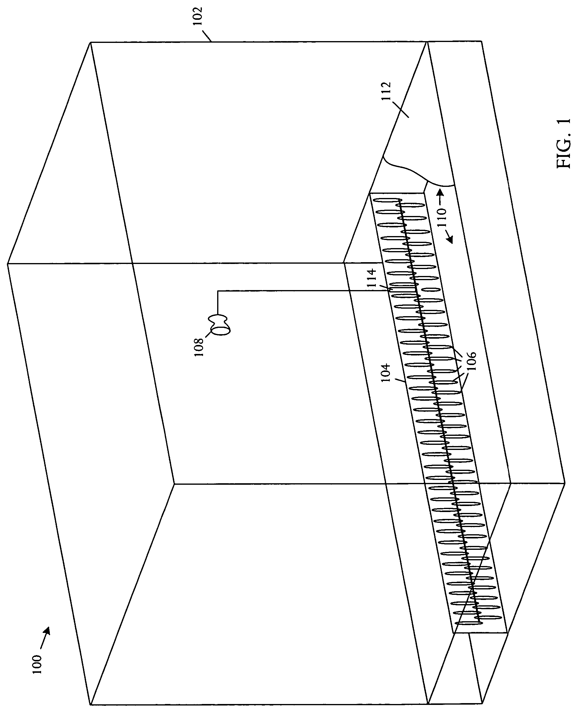
[0016]Referring to FIG. 1, a simplified schematic pictorial diagram illustrates a cut-away view of an embodiment of an airflow distribution control system 100 for usage in a raised-floor data center 102. The system 100 comprises an under-floor partition 104 with a controllable flow resistance 106. The airflow distribution control system 100 also comprises a sensor 108. The partition 104 can be selectively positioned in a plenum 110 beneath the raised-floor 112. The sensor 108 is communicatively coupled to the partition 104 and detects a param...


PUM


Abstract

An airflow distribution control system for usage in a raised-floor data center comprises an under-floor partition with a controllable flow resistance and a sensor. The partition is capable of selective positioning in a plenum beneath the raised-floor. The sensor is communicatively coupled to the partition and detects a parameter indicative of airflow distribution and controls the flow resistance based on the parameter.

Description

BACKGROUND OF THE INVENTION[0001]Electronic systems and equipment such as computer systems, network interfaces, storage systems, and telecommunications equipment are commonly cooled using a pressurized under-floor plenum. Hot air exhausted by electrical equipment in a data center room is drawn into Computer-Room Air Conditioning (CRAC) units via powerful fans in the CRAC units. The CRAC fans cool the hot air by forcing the air through a liquid-to-air heat exchanger. Pressurized cooling air then enters a plenum beneath the data center floor. Cooled air is distributed to the equipment in the room by placing floor tiles with perforations in close proximity to the cool air inlet vents of the equipment.[0002]Typically, during final stages of a data center upgrade or new construction, airflow through the perforated tiles is measured to plan for sufficient cooling to meet expected room equipment heat loads. Adjustments are made to the quantity and placement of the perforated tiles and CRAC...

Claims


Application Information

Patent Timeline
Patent Type & Authority Patents(United States)
IPC IPC(8): H05K5/00F24F3/044F24F11/00F24F11/76H05K7/20
CPCF24F3/044F24F11/0001H05K7/20745H05K7/20836Y02B30/767F24F11/047F24F11/75Y02B30/70E04B5/48F24F7/10F24F13/068F24F13/10F24F11/74F24F11/76
Inventor MALONE, CHRISTOPHER G.
Owner HEWLETT-PACKARD ENTERPRISE DEV LP
Why Eureka
Try Eureka