Production of liquid fuels by a concatenation of processes for treatment of a hydrocarbon feedstock

a hydrocarbon feedstock and process technology, applied in the direction of gasification process details, inorganic chemistry, combustible gas production, etc., can solve the problems of limited economic advantage, achieve maximum carbon conversion, reduce or upgrade naphtha, and limit costly adjustments

Active Publication Date: 2007-05-08
INST FR DU PETROLE +1
View PDF3 Cites 102 Cited by
  • Summary
  • Abstract
  • Description
  • Claims
  • Application Information

AI Technical Summary

Benefits of technology

[0053]One advantage of the invention is therefore to maximize the conversion of the carbon of the feedstock into heavy liquid fuels such as gas oil and / or kerosene. It also makes it possible to reduce or to upgrade the naphtha that is produced by this type of process.
[0054]Another advantage of the invention is to limit the costly adjustments to increase the H2 / CO molar ratio during the stage for purification of the synthesis gas.
[0055]Another advantage of the invention is to maximize the conversion of tars and light hydrocarbons in the gasification stage while limiting the reduction of the H2 / CO molar ratio that is induced by the secondary high-temperature stage.
[0056]Another advantage is the possibility of reducing the purge fraction of the gaseous effluents of the Fischer-Tropsch synthesis.DESCRIPTION OF THE FIGURES
[0057]Other advantages, details and characteristics of the invention shall emerge more clearly in the description of the two embodiments illustrated in FIGS. 1 and 2. These embodiments are provided by way of example and do not exhibit any limiting nature. This illustration of the process of the invention does not comprise all the components that are necessary to its implementation. Only the elements that are necessary to the comprehension of the invention are shown there, whereby one skilled in the art can complete this representation to implement the invention.
[0058]In the embodiments that are shown in FIGS. 1 and 2, the process of the invention comprises the following separate zones:

Problems solved by technology

It is thus sought to reduce or to upgrade the naphtha that is produced by this type of process, whereby the latter exhibits only a limited economic advantage.

Method used


Image

  • Production of liquid fuels by a concatenation of processes for treatment of a hydrocarbon feedstock

Examples


example 1

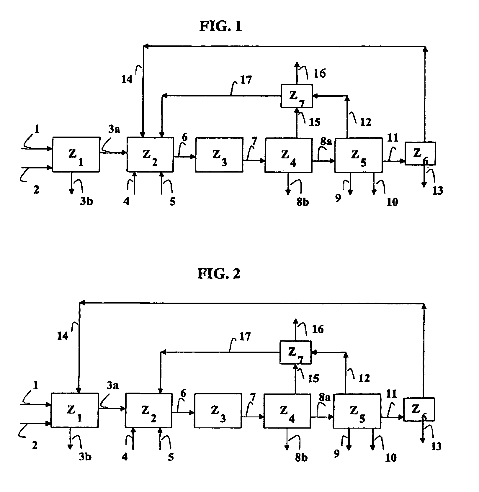
[0079]This example is based on the computer modeling of a concatenation of processes for conversion of biomass into synthesis gas then conversion of said synthesis gas into liquid fuels according to FIG. 1, with the exception of the recycling of top gas and the recycling of naphtha produced in the separation zone, which are not carried out. In other words, the flow rates of streams 14 and 17 are zero. The modeling was carried out by the Pro II® software marketed by the SIMSCI Company.

[0080]Calculations are carried out for an installation that has a 50-ton capacity per hour of dry-base biomass, operating at 0.4 MPa (megapascals). The biomass corresponds to sawdust whose solid particles have a diameter of between 1 and 4 mm and a ratio of length to diameter, L / D, of between 1 and 3. The biomass is introduced in the presence of a conveying gas that corresponds to the combustion fumes that consist of nitrogen and carbon dioxide.

[0081]The biomass is introduced into gasification zone Z1 w...

example 2

[0090]A computer simulation is carried out based on Example 1, with the exception of the top gas that is produced in Fischer-Tropsch section Z4, which is recycled at the inlet of secondary gasification zone Z2 with a purge level of 15% so as to avoid excessive accumulations of nitrogen in the synthesis gas loop. The cumulative production of gas oil and kerosene is 9550 kg / hour, or a yield of 19.1% by weight of dry-base biomass.

[0091]Table No. 2 below sums up the various flows of the process concatenation.

[0092]

TABLE 2Flux en kg / hr123a3b45678a8bBiomasse sèche50000N250070500700032175321881300H20282255908057CO0196394558037442CO21679024695186342691H2O35523287642317237124049Goudrons0176Résidus carbonés6898CH404598C2–C4C5–C93581C10–C143189C15–C196351TOTAL568863552385701670900123652807491325124049Flux en kg / hr91011121314151617Biomasse sècheN20001300032058501927168H2054882466CO1639304503349CO26433283002829H2O46136571114Goudrons0000Résidus carbonésCH41815902451363C2–C43001847443.81871.1C5–C9...

example 3

According to the Invention

[0094]A computer simulation is carried out based on Example 1, with the exception of the top gas that is produced in Fischer-Tropsch section Z4, which is recycled at the inlet of secondary gasification zone Z2. It is the same for the naphtha that is produced in final separation zone Z5 of the liquid fuels. The purge levels are respectively 15% on the top gas and 1% on the naphtha so as to prevent excessive accumulations of undesirable products in the synthesis gas loop. The cumulative production of gas oil and kerosene is 12,504 kg / hour, or a yield of 25.0% by weight of dry-base biomass.

[0095]Table No. 3 below sums up the various flows of the process concatenation.

[0096]

TABLE 3Flux on kg / hr123a3b45678a8bBiomasse sèche50000N2500705007000321753217600H20262274337931CO0196395861151643CO21879024895171832613H2O35623287641609145130754Goudrons0175Résidus carbonés6699CH404598C2–C4C5–C94689C10–C144175C15–C198329TOTAL568863552385701670800131495850241719530754Flux on ...


PUM

PropertyMeasurementUnit
temperatureaaaaaaaaaa

Abstract

The invention relates to an installation and a process for the production of liquid fuels starting from a solid feedstock that contains the organic material in which:a) the solid feedstock is subjected to a gasification stage so as to convert said feedstock into synthesis gas,b) the synthesis gas is subjected to a purification treatment,c) the purified synthesis gas is subjected to a conversion stage that comprises the implementation of a Fischer-Tropsch-type synthesis so as to convert said synthesis gas into a liquid effluent and a gaseous effluent,d) the liquid effluent is fractionated so as to obtain a gaseous fraction, a naphtha fraction, a kerosene fraction and a gas oil fraction, ande) at least a portion of the naphtha fraction is recycled in gasification stage a).

Description

FIELD OF THE INVENTION [0001]This invention relates to a process for the production of liquid fuels starting from a solid feedstock that comprises organic material, typically biomass. More particularly, the invention relates to a process that comprises a gasification stage of the solid feedstock, a stage for purification of the synthesis gas, and a stage for transformation of the synthesis gas into liquid fuels.PRIOR ART [0002]A large number of patents describe the use of synthesis gas for producing biofuels by a Fischer-Tropsch synthesis with which hydrocracking is often combined. The Fischer-Tropsch synthesis produces gas oil fractions, kerosene fractions, naphtha fractions and a top gas in a more or less significant amount based on the set of operating conditions selected from the Fischer-Tropsch and hydrocracking reaction zones, as well as operating conditions of the downstream distillation train.[0003]U.S. Pat. No. 5,494,653 proposes a method for treatment of a synthesis gas by...

Claims


Application Information

Patent Timeline
Patent Type & Authority Patents(United States)
IPC IPC(8): C07C27/00C10G11/00C01B3/52C10G2/00C10J3/46
CPCC01B3/52C10G2/32C10J3/463C10K3/006C10K3/04C01B2203/0415C01B2203/0475C01B2203/0495C10J2300/0969C10J2300/0973C10J2300/0983C10J2300/0989C10J2300/0993C10J2300/1618C10J2300/1659C10J2300/1807Y02E50/32C10G2300/1011C10G2300/4081C10G2400/02C10G2400/06C10G2400/08Y02P20/145Y02P30/20Y02E50/30
Inventor BAYLE, JEROMEBOISSONNET, GUILLAUMEMARTY, ERICSEILLER, JEAN-MARIE
Owner INST FR DU PETROLE
Why Eureka
Try Eureka