
Marchand-type distributed balun

a balun and distribution balun technology, applied in the direction of impedence networks, coils, electrical devices, etc., can solve the problem of high insertion loss

Active Publication Date: 2007-05-08
STMICROELECTRONICS SRL
View PDF6 Cites 10 Cited by
  • Summary
  • Abstract
  • Description
  • Claims
  • Application Information

AI Technical Summary

Benefits of technology

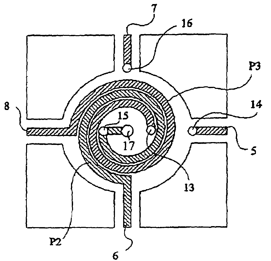
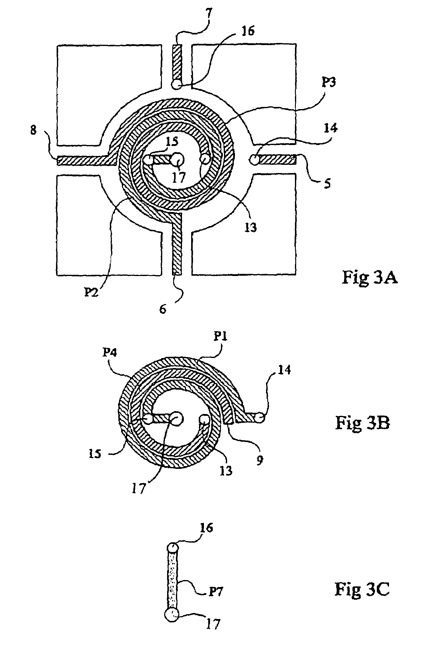
"The present invention provides a new type of balun structure that is smaller and more symmetrical than conventional designs. It achieves this by using a mode-switching transformer with two conductive lines, each made up of two stacked spirals in different metallization levels. The third metallization level is used to transfer outside of the structure a central contact of the winding. The number of vias is limited to five for the entire structure. The spirals are sized based on an inductance value desired for a non-stacked structure, knowing that the value increase is proportional to the square of the number of turns of the stacked structure. These technical effects make the balun structure more efficient and compact while maintaining its performance."

Problems solved by technology

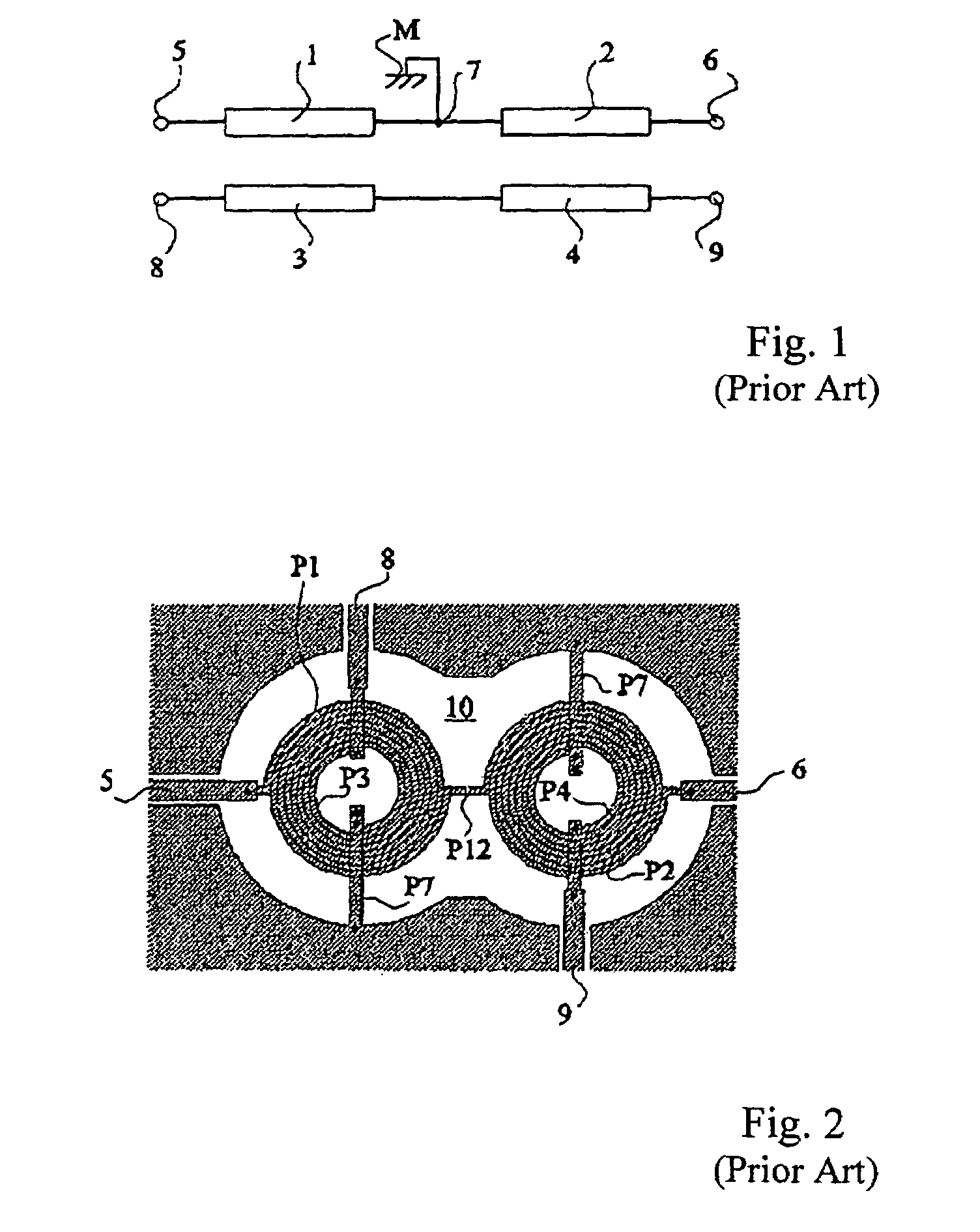
A disadvantage of baluns with coupled lines is linked to the significant size required by the λ / 4 lines which, in addition to a significant bulk, causes high insertion losses.

Method used


Image

  • Marchand-type distributed balun
  • Marchand-type distributed balun
  • Marchand-type distributed balun

Examples


Embodiment Construction

[0027]The same elements have been referred to with the same reference numerals in the different drawings. For clarity, only those elements which are necessary to the understanding of the present invention have been shown in the drawings and will be described hereafter. In particular, the application circuits connected upstream and downstream of a mode-switching transformer according to the present invention have not been described in detail, the present invention applying whatever exploitation is made of the transformer and being perfectly compatible with conventional uses of a transformer with coupled lines.

[0028]A feature of the present invention is to interlace or interdigit the windings constitutive of a mode-switching transformer in two metallization levels. In other words and in simplified fashion, the present invention provides folding on each other while interlacing them the two laterally spaced apart portions of the conventional structure of FIG. 2.

[0029]Contrary to all exp...


PUM

PropertyMeasurementUnit
insertion lossaaaaaaaaaa
conductiveaaaaaaaaaa
inductanceaaaaaaaaaa

Abstract

A mode-switching transformer including a first conductive line between two common-mode access terminals and a second conductive line between two differential mode access terminals, the lines being coupled and sized according to a central operating frequency of the transformer, each line being formed of two stacked spirals in two different metallization levels and each spiral of a line being interdigited with a spiral of the other line.

Description

BACKGROUND OF THE INVENTION[0001]1. Field of the Invention[0002]The present invention relates to the field of mode-switching transformers which are used to convert a voltage from a common mode to a differential mode and conversely. Such transformers are generally called “balun” transformers, for “balanced-unbalanced”.[0003]2. Discussion of the Related Art[0004]An example of application of a mode-switching transformer relates to radio frequency transceiver channels, for example, of a mobile phone. This type of application currently uses devices of balun type since, on the antenna side, it most often is a single-ended device.[0005]Two main categories of mode-switching transformers are known, that is, coupled line baluns or distributed baluns, and baluns with local components. Baluns with coupled lines are formed of conductive tracks coupled to each other, the transformer's operating frequency being conditioned by the line length. Baluns with local components are formed of capacitive a...

Claims


Application Information

Patent Timeline
Patent Type & Authority Patents(United States)
IPC IPC(8): H03H7/42H01F5/00
CPCH03H7/42
Inventor EZZEDDINE, HILAL
Owner STMICROELECTRONICS SRL
Learn More