Method and apparatus for forming transient response characteristics

a transient response and characteristic technology, applied in the field of transient response characteristics, can solve the problems of large circuit area required to realize each segment, difficulty in realizing that characteristic, and aggravate the distortion of the dac, so as to reduce the transient response error

Active Publication Date: 2007-05-08
TEXAS INSTR INC
View PDF4 Cites 9 Cited by
  • Summary
  • Abstract
  • Description
  • Claims
  • Application Information

AI Technical Summary

Benefits of technology

[0007]A general object of the present invention is to provide a method and device for forming transient response characteristics that can reduce the transient response error.
[0009]According to a second aspect of the present invention, the method for forming transient response characteristics can have a step of generating the transient response in the first polarity direction of the aforementioned circuit and the transient response in the second polarity direction opposite to the aforementioned first polarity and a step of combining the transient responses in the aforementioned first and second polarity directions to generate a composite transient response. The aforementioned transient response generating step can include a step of generating the transient response in the aforementioned first polarity direction in a first circuit used as the aforementioned circuit and a step of generating the transient response in the aforementioned second polarity direction in a second circuit that is virtually equivalent to the aforementioned first circuit and is used as the aforementioned circuit. Also, the transient response characteristic of the aforementioned first circuit may have virtually the same tendency regarding the error between the transient response in the first polarity direction and the transient response in the second polarity direction as the transient response characteristics of the aforementioned second circuit. The aforementioned composite transient response characteristic may have virtually equivalent transient response characteristic in the first and second polarity directions so that the error between the transient responses in the first and second polarity directions of the aforementioned circuit can be reduced. The aforementioned first and second circuits can also be different from each other. The transient response in the aforementioned first polarity direction may be either a rising transient response or a falling transient response, while the transient response in the aforementioned second polarity direction is the other transient response.
[0011]According to a fourth aspect of the present invention the method for reducing the error in the response of a circuit device has, the transient response characteristic in a first polarity direction of the response of the circuit device and the transient response characteristic in a second polarity direction opposite to the first polarity are each formed by combining the transient response characteristics in the first and second polarity directions of a prescribed circuit element in the aforementioned circuit device.
[0013]According to a sixth aspect of the present invention, in the aforementioned transient response generating circuit, the aforementioned first and second circuits can be virtually equivalent to each other. Also, each of the aforementioned first and second circuits can be any circuit among plural circuits that are virtually equivalent to each other. The transient response characteristic of the aforementioned first circuit has virtually the same tendency regarding the error between the transient response in the first polarity direction and the transient response in the second polarity direction as the transient response characteristic of the aforementioned second circuit. In this case, the aforementioned composite transient response characteristic may have virtually equivalent transient response characteristics in the first and second polarity directions so that the error between the transient responses in the first and second polarity directions of the aforementioned circuit can be reduced.
[0018]According to an eleventh aspect of the present invention, the transient response characteristics in the first and second polarity directions of the aforementioned error-reduced output can be virtually equivalent to each other. Also, the transient response characteristic in the aforementioned first polarity direction and the transient response characteristic in the aforementioned second polarity direction of the aforementioned error-reduced output can each be the combination of the transient response characteristic in the aforementioned first polarity direction and the transient response characteristic in the aforementioned second polarity direction of the aforementioned first circuit. The aforementioned error reducing circuit can be connected properly to receive the aforementioned first input and the first output of the aforementioned first circuit. In this case, the aforementioned error reducing circuit can have A) a second circuit that receives a second input and generates a second output, this second circuit being virtually equivalent to the aforementioned first circuit and B) a matching circuit that is connected to the aforementioned first and second circuits and generates the aforementioned error-reduced output by matching the transient response characteristics. The aforementioned error-reduced output has matched transient response characteristics in the first and second polarity directions. The aforementioned matching circuit can also have A) an inverting circuit that inverses the aforementioned first input to generate the aforementioned second input and B) a synthesizing circuit that combines the aforementioned first and second outputs to generate the aforementioned error-reduced output. The aforementioned first input is applied to the aforementioned first circuit to generate the aforementioned first output. The aforementioned second input is applied to the aforementioned second circuit to generate the aforementioned second output. In this way, one of the transient responses in the aforementioned first and second polarity directions of one the aforementioned first and second circuits can be generated at the same time with the other transient response among the transient responses in the aforementioned first and second polarity directions of the other circuit among the aforementioned first and second circuits.

Problems solved by technology

In the actual circuit, however, it is difficult to realize that characteristic.
In the actual circuit, however, the influence of the circuit configuration of each segment and mismatches of the circuit elements used causes differences to occur between the rising transient response characteristic and the falling transient response characteristic, and such differences will aggravate the distortion of the DAC.
When using this method, however, a very large circuit area is required to realize each segment.
As a result, the circuit configuration becomes complicated, and the circuit area is increased.
The aforementioned transient response error also occurs in many other electrical circuits or circuit devices besides the DAC.

Method used


Image

  • Method and apparatus for forming transient response characteristics
  • Method and apparatus for forming transient response characteristics
  • Method and apparatus for forming transient response characteristics

Examples


Embodiment Construction

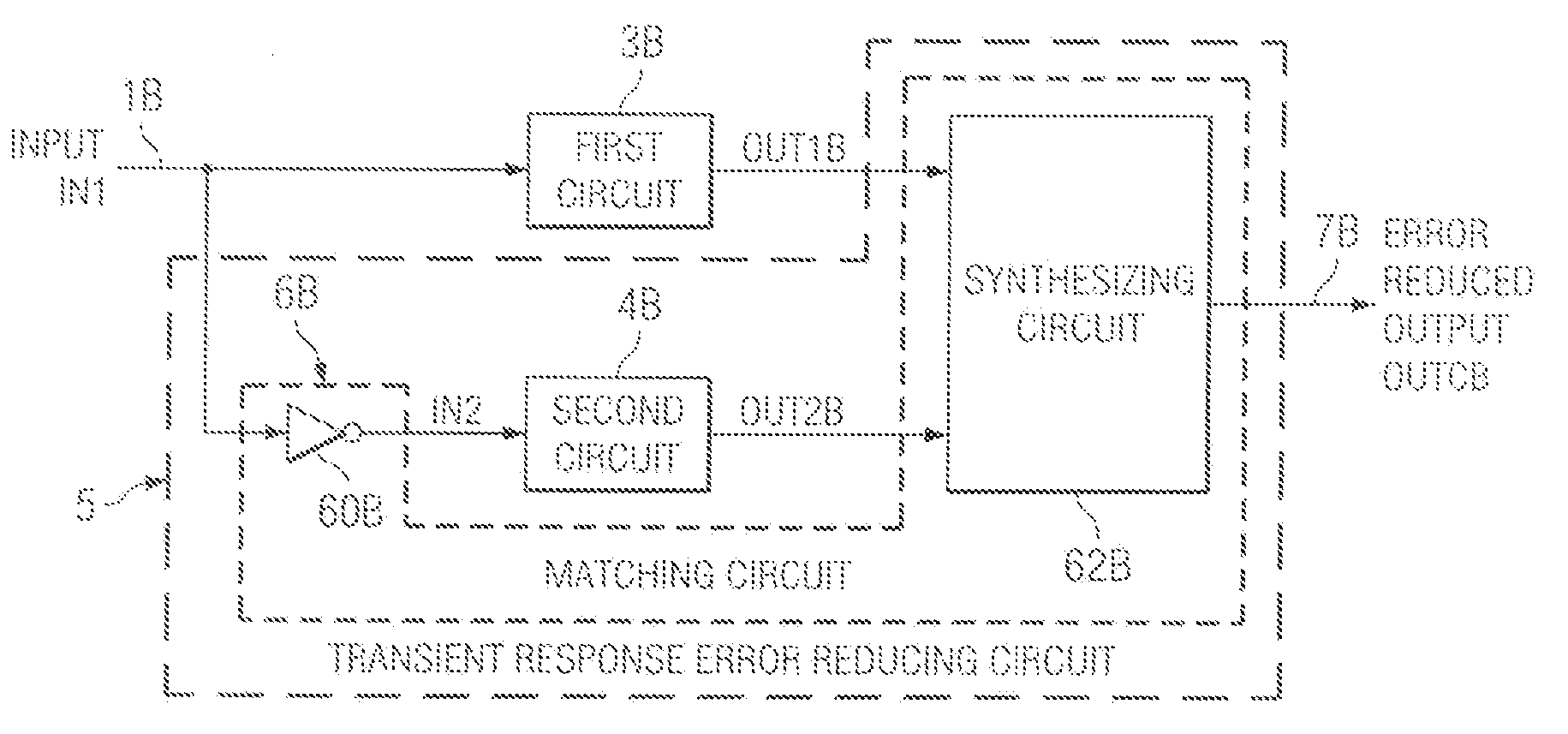
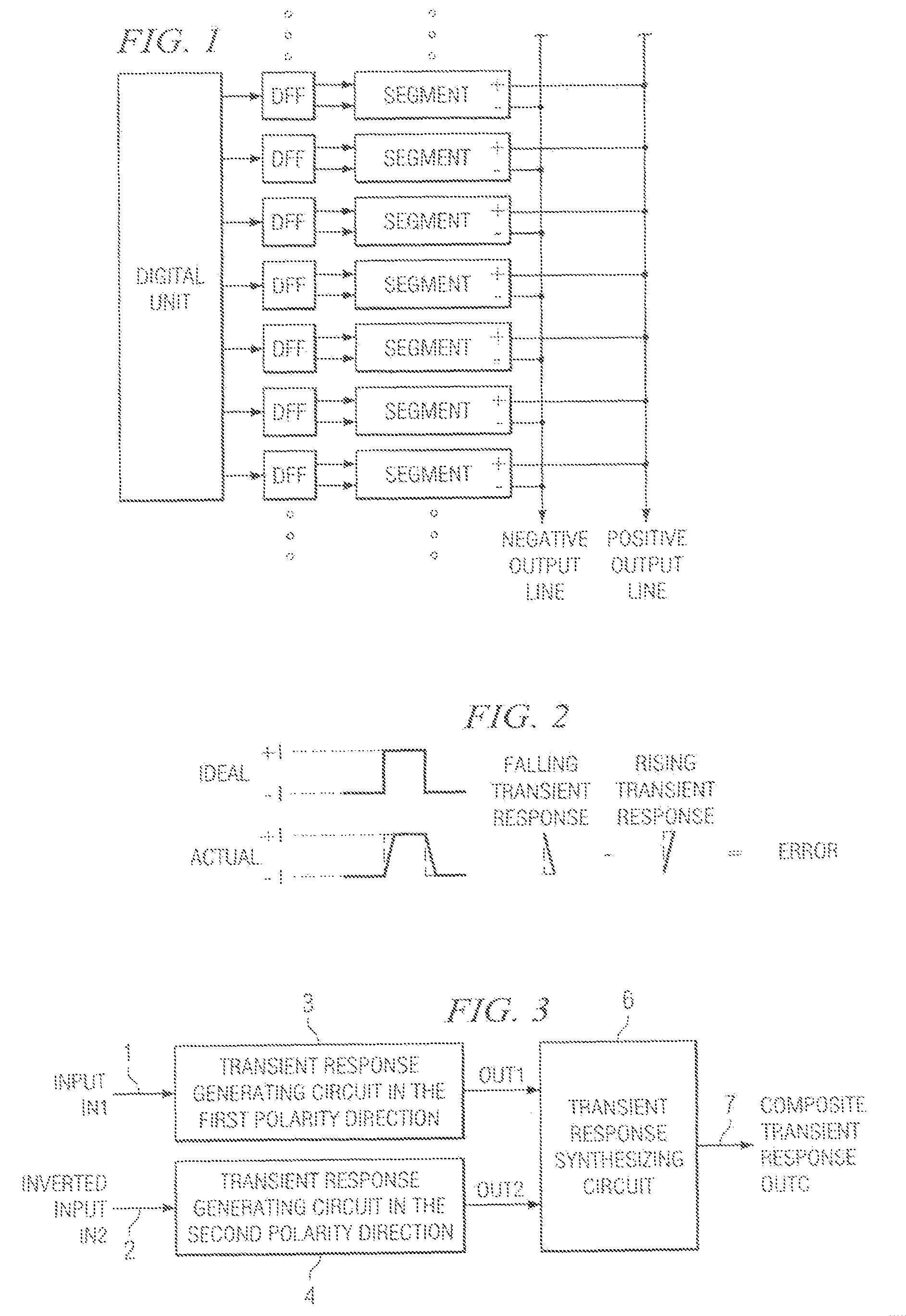
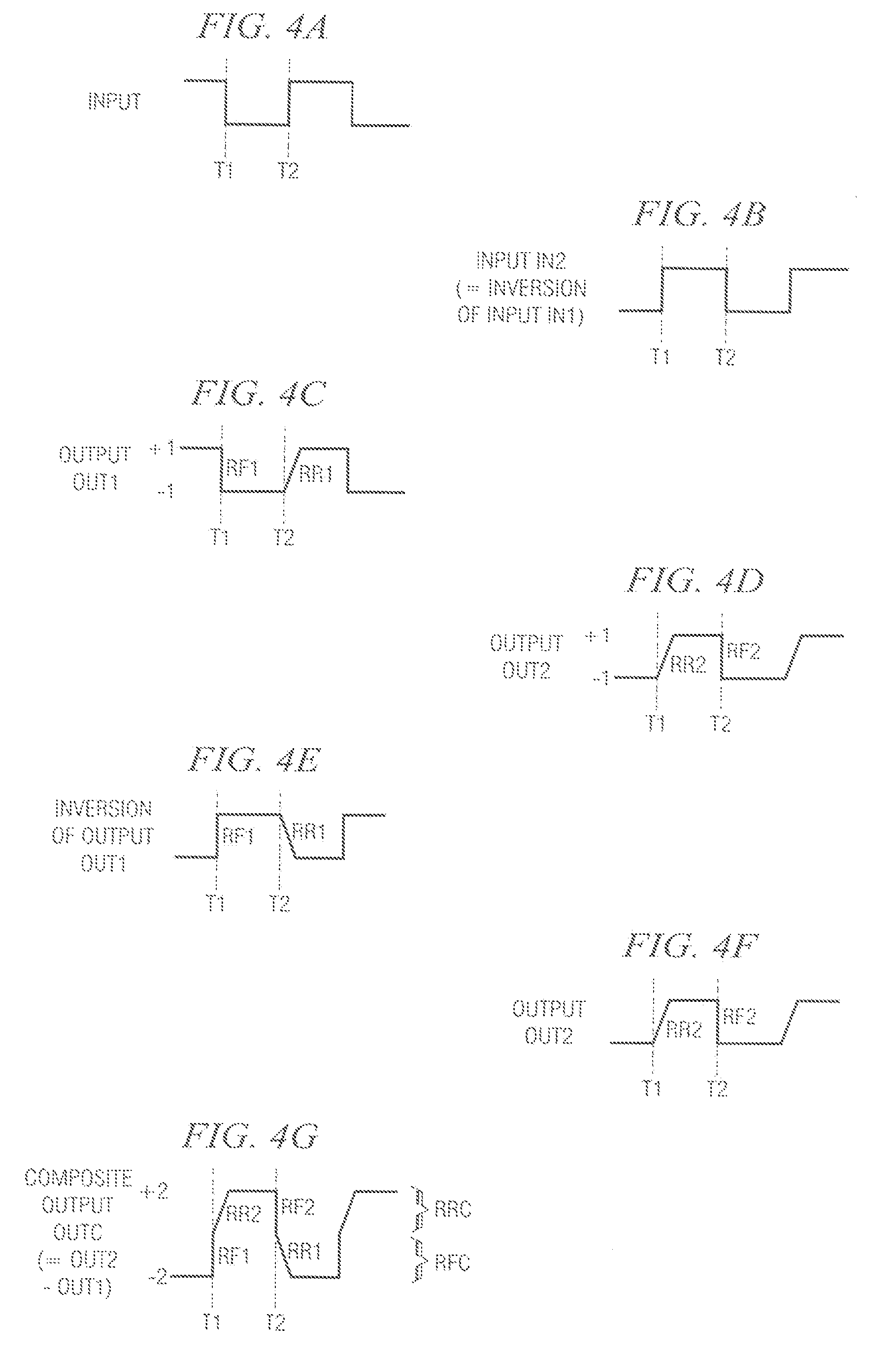
[0043]According to the present invention, transient response characteristics with reduced transient response error can be formed. The offset caused by the transient response error can also be reduced. Also, according to the present invention, the distortion performance of D / A converters can be improved. In the case of a D / A converter having plural segments, the transient response error can be reduced so that the distortion performance can be improved without increasing the number of segments. Consequently, a desired distortion performance can be realized using a circuit area smaller than the area required in the conventional technology to improve the distortion performance. In addition, by matching the rising and falling transient responses, the transient response error can be reduced more easily than in the conventional technology. In other words, the transient response error can be reduced very easily by using at least two identical circuits instead of by adding complicated circui...


PUM


Abstract

Transient response generating circuit A has a first circuit 3 that generates transient response OUT1 in a first polarity direction, a second circuit 4 that generates transient response OUT2 in a second polarity direction opposite to the first polarity, and a transient response synthesizing circuit 6 that combines the transient response OUT1 in the first polarity direction and the transient response OUT2 in the second polarity direction to generate composite transient response OUTC.

Description

FIELD OF THE INVENTION[0001]The present invention pertains to a method and device for forming transient response characteristics of circuit devices including op-amps, digital-analog (D / A) converters (DAC), and other electrical circuits. In particular, the present invention pertains to a method and device used to reduce the transient response error of these circuit devices.BACKGROUND OF THE INVENTION[0002]FIG. 1 is a block diagram illustrating an example of a conventional segment DAC. This segment DAC is comprised of any number of segments, and the same number of D-type flip-flops (DFF). Each of the segments included in the DAC receives a 1-bit signal from the Q output and Q* (* means inversion) output of a DFF from the digital part. According to that 1-bit signal, each segment outputs a signal of “+1” or “−1” in the form of a differential signal (positive output and negative output). The positive output and negative output that constitute each differential output obtained from these...

Claims


Application Information

Patent Timeline
Patent Type & Authority Patents(United States)
IPC IPC(8): H03M1/66
CPCH03M1/0863H03M1/0682H03M1/745H03M1/747
Inventor IDO, TORUISHIZUKA, SOICHIRO
Owner TEXAS INSTR INC
Why Eureka
Try Eureka