Coherent light despeckling

a light speckling and coherent technology, applied in the field of coherent light speckling, can solve the problems of varying degrees of artifacting, reducing coherent light speckling, and difficulty in discerning the tiger by the ey

Inactive Publication Date: 2007-05-08
INTEL CORP
View PDF30 Cites 9 Cited by
  • Summary
  • Abstract
  • Description
  • Claims
  • Application Information

AI Technical Summary

Problems solved by technology

If the tiger remains stationary, our eye has a difficult time discerning the tiger, due to his camouflaged pattern.
A problem, similar to reducing coherent light speckling, occurs in the field of halftone printing.
Many half-toning algorithms are known, but they suffer from varying degrees of artifacting, such as banding, in which the eye perceives extra structure in the dots.
There are some problems with this solution.
That portion of the light which passes through the rotational center of the plate will receive essentially zero despeckling; in order to avoid that, it would be necessary to use a plate having a diameter more than twice the diameter of the light beam at that location—so the entire image could be passed through the plate off to the side of the rotational center—which results in a larger overall display system, a larger and more expensive plate, and larger and more expensive rotation mechanism.
Another alternative might be to oscillate the rotating plate so it does not have a consistent rotational center, but that would introduce undesirable mechanical problems such as vibration.
Neither the halftone printing art nor this prior art despeckling system makes any mention or use of blue noise characteristics for despeckling.

Method used


Image

  • Coherent light despeckling
  • Coherent light despeckling
  • Coherent light despeckling

Examples


Embodiment Construction

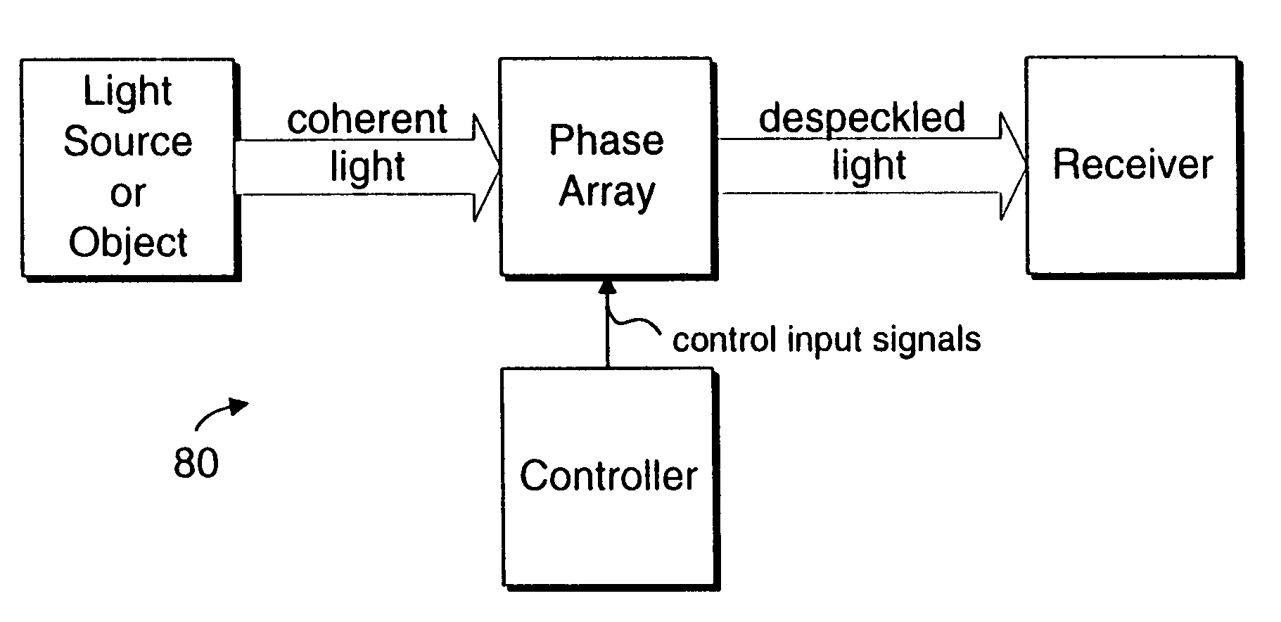
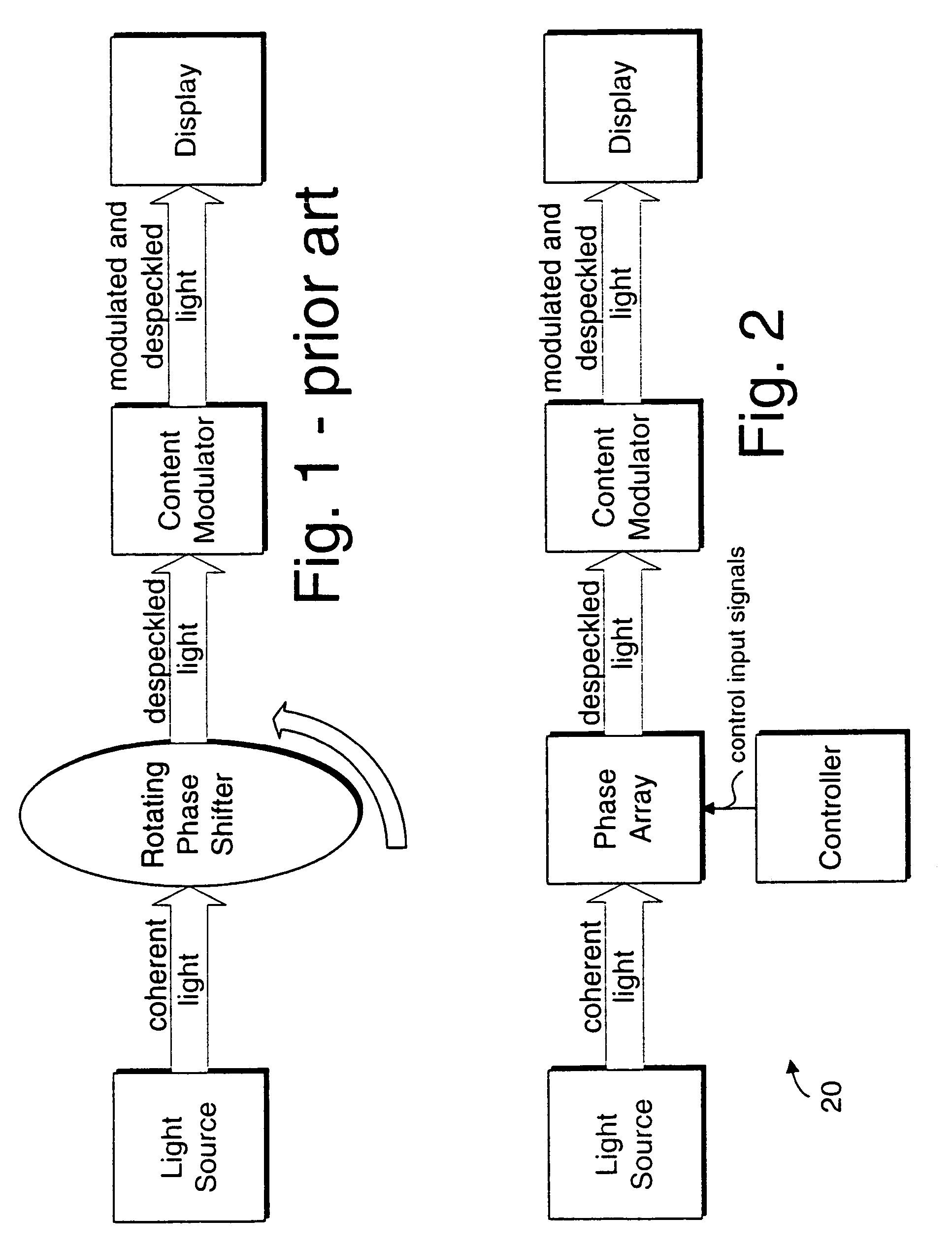
[0029]FIG. 2 shows a display system 20 according to one embodiment of this invention. The display system may be any display system in which a coherent light source is employed, including but not limited to: televisions, display televisions, computer monitors, projectors, movie theater projectors, direct-to-eye projectors, head-up displays, and the like.

[0030]The light source may provide only one base color for the system, such as red, or it may provide a plurality of colors. One example of a suitable light source is a laser. The light source may be the sole light source in the display system, or it can be used in conjunction with other light sources that may, themselves, be coherent or non-coherent.

[0031]Light from the light source may exhibit coherency in one or more dimensions, under one or more conditions, or at one or more times. It is not necessary that the light actually exhibit coherency at all times, nor under all conditions, nor that coherency would cause speckling which is...


PUM


Abstract

A display device or a receiver device for use with coherent light. A controller applies phase shift values to a multi-region phase array at a frequency sufficiently higher than the flicker fusion rate of the human eye or other intended receiver in order to remove the perception of speckling artifacts which would otherwise appear due to the coherency of the light.

Description

[0001]This is a continuation of prior application Ser. No. 09 / 706,494, filed Nov. 2, 2000 now U.S. Pat. No. 6,738,105.BACKGROUND OF THE INVENTION[0002]1. Technical Field of the Invention[0003]The present invention relates to removal of low-frequency pattern content from coherent light to avoid the perception of speckling.[0004]2. Related Application[0005]U.S. patent application Ser. No. 09 / 706,502 entitled “Quantum Random Number Generator” co-pending herewith and filed by Eric C. Hannah, co-inventor hereof.[0006]3. Background Art[0007]A coherent light beam will exhibit interference fringes if there are plural propagation paths that the light can take from the light source to the display device. Imaging systems use focusing elements such as lenses, mirrors, and the like to direct light onto a display device. Each of these lenses etc. may offer a vast number of propagation paths for the light to reach any given display surface location or pixel. This problem is very analogous to the f...

Claims


Application Information

Patent Timeline
Patent Type & Authority Patents(United States)
IPC IPC(8): H04N9/12H04N5/74H04N9/31
CPCH04N5/7416H04N9/3129
Inventor HANNAH, ERIC C.O'CONNOR, MICHAEL
Owner INTEL CORP
Why Eureka
Try Eureka