Hard disk drive (HDD) assembly of small form-factor HDD shock-mounted in frame having dimensions of larger form-factor HDD

a technology of hard disk drives and shock-mounted frames, which is applied in the field of system for mounting and supporting an hdd, can solve the problems of reducing cost, time-consuming and labor-intensive re-design of the host system, and achieve the effect of high stiffness

Inactive Publication Date: 2007-05-08
WESTERN DIGITAL TECH INC
View PDF14 Cites 20 Cited by
  • Summary
  • Abstract
  • Description
  • Claims
  • Application Information

AI Technical Summary

Benefits of technology

[0008]The smaller form-factor HDD is supported in the frame by a pair of mount assemblies, with each mount assembly being attached to one of the sides or ends of the HDD substantially at the HDD's height midplane (i.e., close to or at the vertical center-of-gravity of the HDD). Each mount assembly has two cantilever arms that lie substantially in the HDD's height midplane. The free ends of the cantilever arms are attached to a side or end of the frame substantially at the frame's height midplane. Damping material may be located on both sides of the cantilever arms and clamping plates used to compress the damping material against the cantilever arms when the arms are fastened to the frame. The mount assemblies with the spring-like cantilever arms and the compressed damping material thus act as a highly-damped nonlinear spring system that provides mechanical-shock resistance for the HDD in a direction normal to the planes of the disks and high stiffness in a direction parallel to the planes of the disks.
[0009]The frame may have a 2.5 in. HDD form-factor and the HDD may be a 1.8 in. HDD, with the electrical connector on the 1.8 in. HDD being along its side and the electrical connector exposed at the frame being along the frames' end, as required by the specifications of a 2.5 in HDD. In this embodiment of the invention, the 1.8 in. HDD is mounted to the frame in a position inverted (i.e., “upside down”) from the position a 2.5 in. HDD would present. This inverted mounting of the HDD within the frame enables the electrical cable to be a simple flat cable with no bends but with all of its conductive traces lying in substantially the same plane, thereby permitting the cable to be located entirely inside the frame within the limits of the frame's height.

Problems solved by technology

Once a particular form-factor HDD has been chosen for use in the host system, it can be costly and time-consuming to re-design the host system to accommodate a smaller form-factor HDD.
As the capacity and availability of 1.8 in HDDs increase and their cost decreases, notebook manufactures may want to switch to this smaller form-factor HDD but do not want to redesign their computers.

Method used


Image

  • Hard disk drive (HDD) assembly of small form-factor HDD shock-mounted in frame having dimensions of larger form-factor HDD
  • Hard disk drive (HDD) assembly of small form-factor HDD shock-mounted in frame having dimensions of larger form-factor HDD
  • Hard disk drive (HDD) assembly of small form-factor HDD shock-mounted in frame having dimensions of larger form-factor HDD

Examples


Embodiment Construction

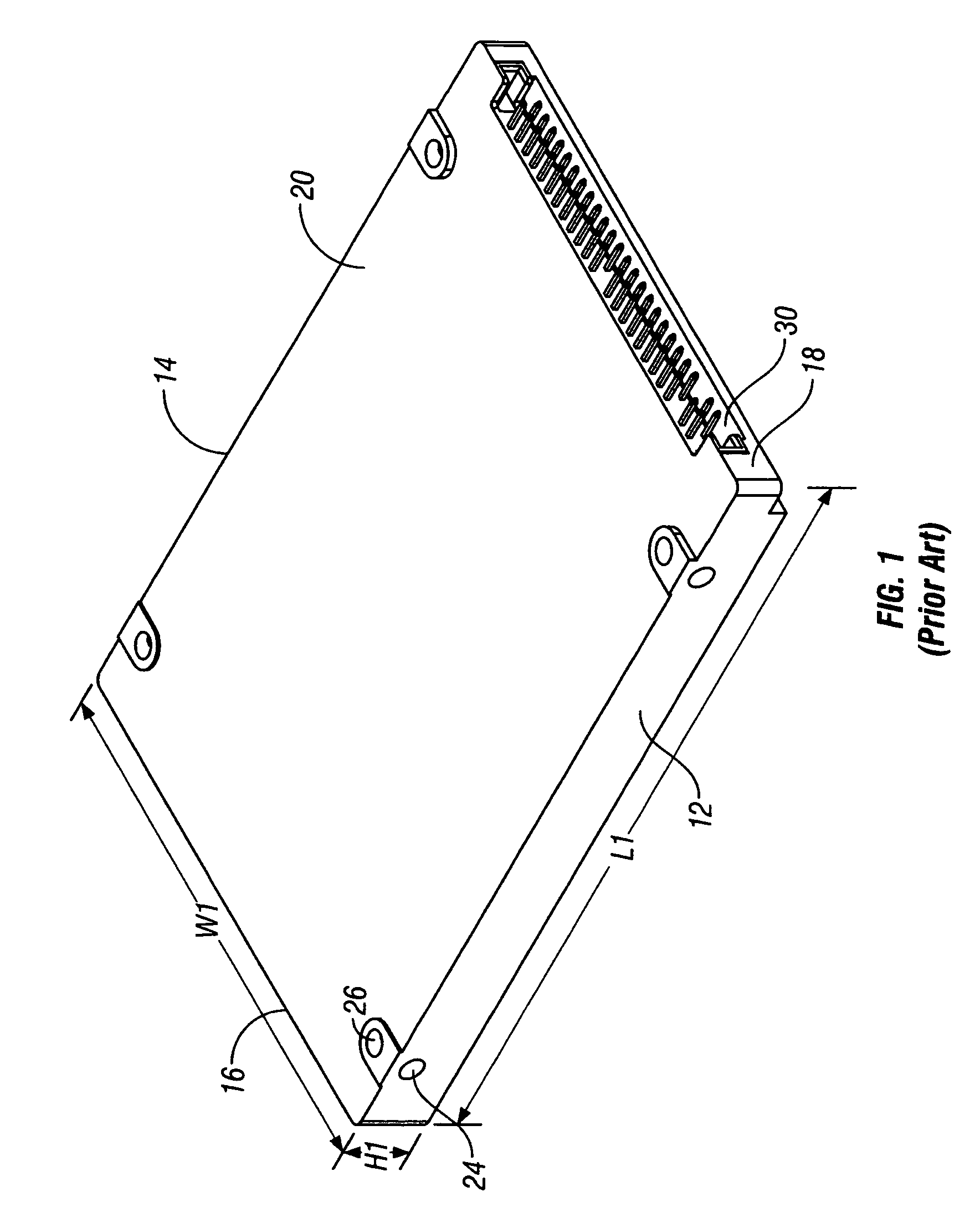
[0017]FIG. 1 is an isometric view of a 2.5 in. form-factor hard-disk-drive (HDD) as is known in the prior art. The HDD has sides 12, 14; ends 16, 18; a bottom surface 20 and a top cover (not shown). The base plate that supports the motor for the rotatable disks is the HDD “bottom”. The disks are parallel to the top cover and bottom surface 20. The HDD is attached to its host system, such as a notebook computer, by screws secured into tapped holes, such as typical holes 24, 26. Electrical connection is made to the host system with a male connector pin header 30. The header 30 is shown in the “upright” configuration relative to bottom surface 20. The HDD's exterior specifications, including the dimensions of length L1, width W1 and height H1, the positioning of the header 30 at end 18, and the location of the tapped holes are all determined by industry-standard specifications. In this 2.5 in. form-factor HDD the pin header 30 is male, but in other form-factor HDDs the pin header may b...


PUM

PropertyMeasurementUnit
length L1aaaaaaaaaa
width W1aaaaaaaaaa
height H1aaaaaaaaaa

Abstract

The invention is a hard-disk-drive (HDD) assembly that includes a flame having the exterior dimensions of a particular form-factor HDD, an HDD with a form-factor smaller than the frame, a pair of mount assemblies that support the HDD entirely within the larger form-factor frame, and an electrical cable located entirely within the frame and having one end connected to the HDD and the other end exposed to the frame exterior at the position determined by the specifications of the larger form-factor. The HDD assembly thus presents a smaller form-factor HDD as a fully plug-compatible alternative to a larger form-factor HDD. The mount assemblies have spring-like cantilever arms in contact with damping material to provide a highly-damped nonlinear spring system that provides mechanical-shock resistance for the HDD in a direction normal to the planes of the disks and high stiffness in a direction parallel to the planes of the disks.

Description

BACKGROUND OF THE INVENTION[0001]1. Field of the Invention[0002]This invention relates generally to hard disk drives (HDDs), and more particularly to a system for mounting and supporting an HDD in an assembly that can be attached to a host system, such as a notebook computer.[0003]2. Description of the Related Art[0004]Magnetic recording hard disk drives (HDDs) are used for data storage in a wide range of host systems, including desktop and portable or notebook computers, servers, and electronic consumer devices, such as digital video recorder (DVRs) and portable MP3 players. All HDDs fall into one or more general size categories, based roughly on the diameter of the disk or disks inside the HDD. The most common HDD sizes in use today are 3.5 in., 2.5 in., 1.8 in., and 1 in. HDDs. In addition, most HDDs are manufactured to “form-factor” specifications or standards set by one or more industry-standards organizations. These specifications define the dimensions, mounting hole locations...

Claims


Application Information

Patent Timeline
Patent Type & Authority Patents(United States)
IPC IPC(8): G11B17/00G11B33/14G11B5/012
CPCG11B33/08G11B33/122G11B33/124
Inventor ALBRECHT, DAVID W.AOYAGI, AKIHIKOHUANG, FU-YINGISHII, TOMOKAZUZENG, QINGHUA
Owner WESTERN DIGITAL TECH INC
Why Eureka
Try Eureka