Rotary anode type X-ray tube
a rotary anode and x-ray tube technology, applied in the direction of x-ray tube electrodes, electrical discharge tubes, electrical apparatus, etc., can solve the problems of large volume of the entire apparatus, inability to rotate smoothly and smoothly the cylindrical rotary structure, and increase the size and weight of each of the members. , to achieve the effect of high reliability, smooth rotation and stable operation
- Summary
- Abstract
- Description
- Claims
- Application Information
AI Technical Summary
Benefits of technology
Problems solved by technology
Method used
Image
Examples
first embodiment
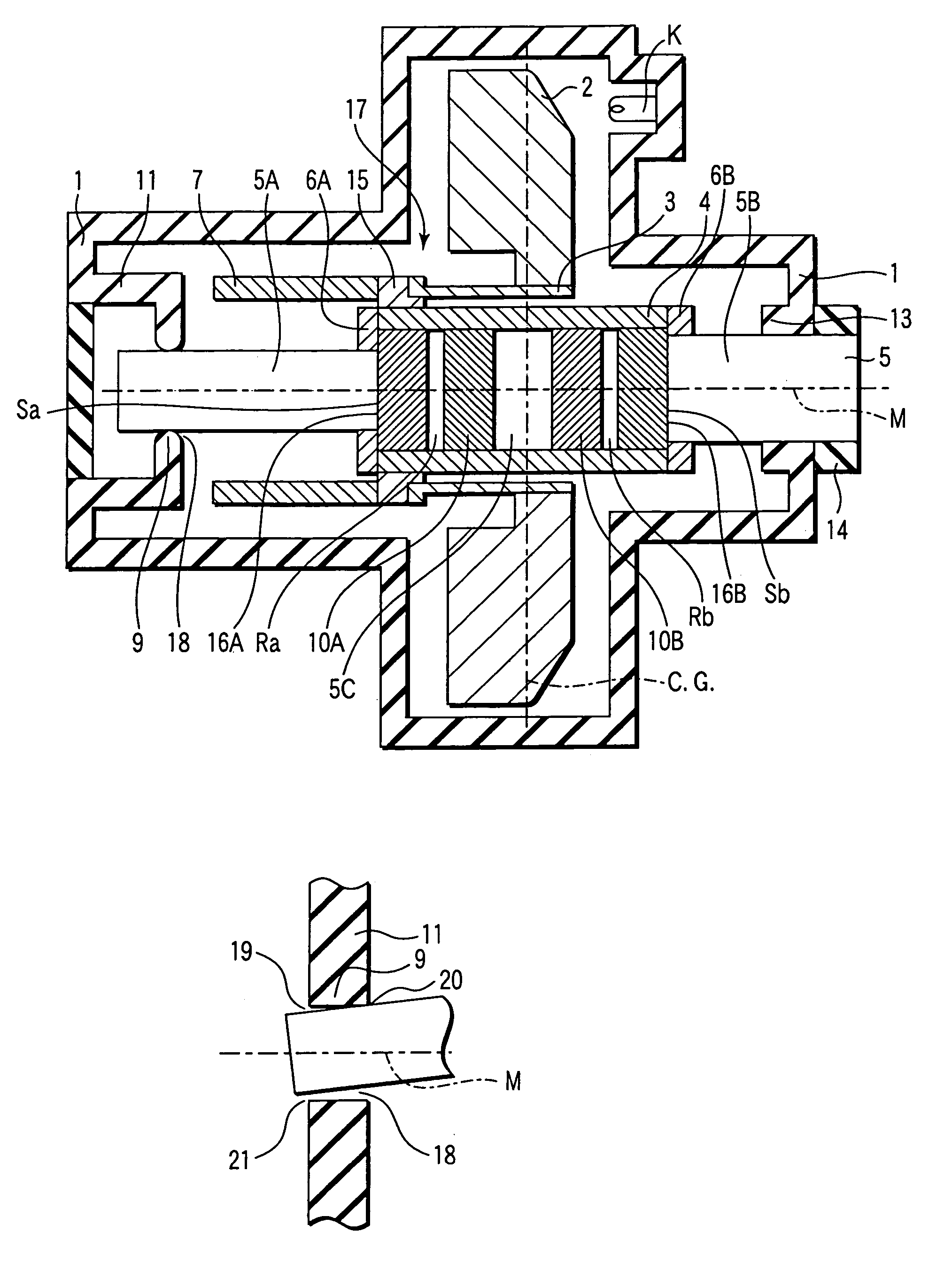
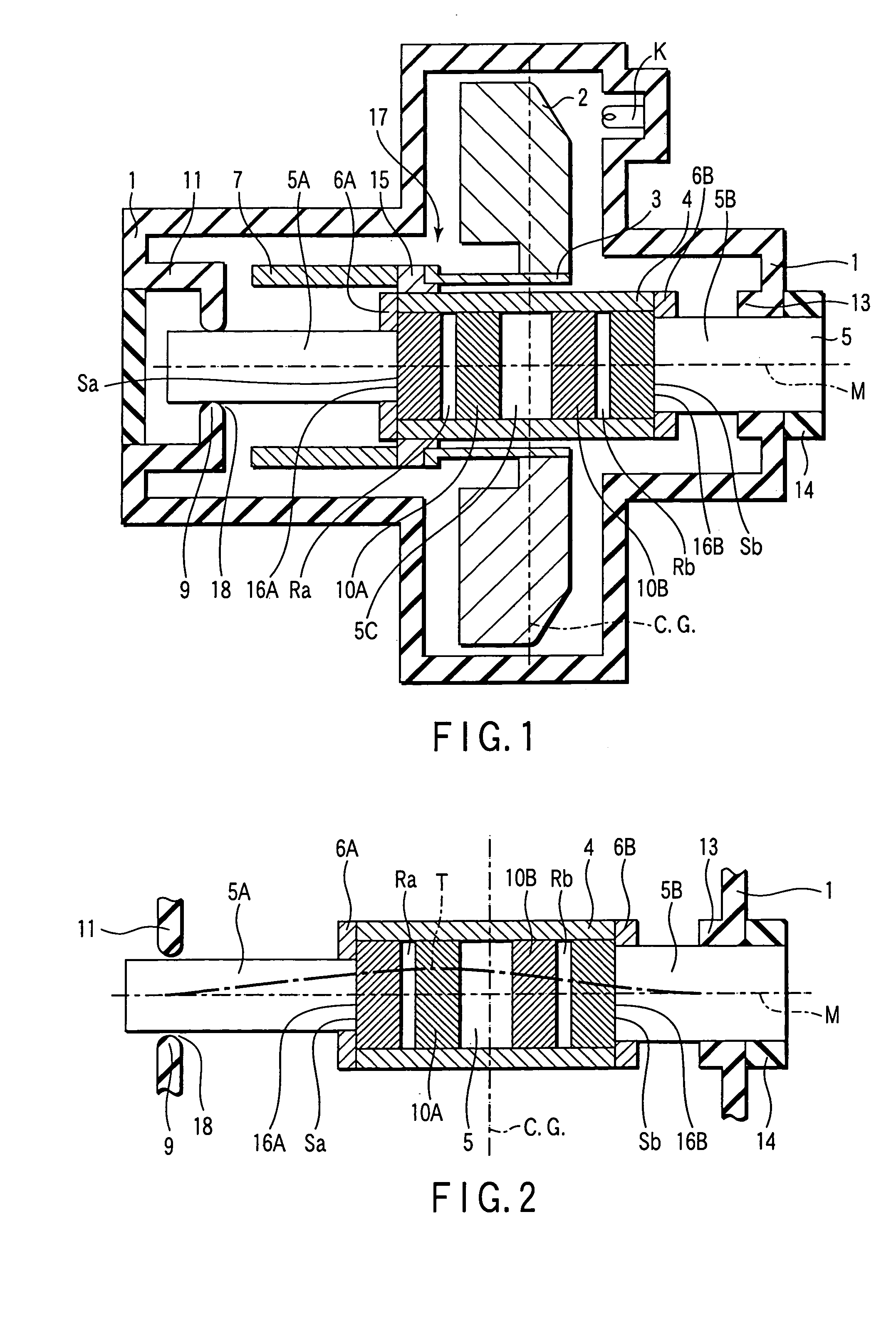
[0058]FIG. 1 is a cross sectional view schematically showing the construction of a rotary anode type X-ray tube according to the present invention.
[0059]As shown in FIG. 1, the rotary anode type X-ray tube of the present invention comprises a vacuum envelope 1 and a rotary anode 2 received in the vacuum envelope 1. The rotary anode 2 is rotated and used as a target. An electron beam emitted from a cathode K is impinged on the rotary anode 2 so as to cause an X-ray to be emitted from the rotary anode 2. The rotary anode 2 is fixed to a cylindrical coupling section 3 and is joined to a cylindrical portion 4 via the cylindrical coupling section 3 and a member 15 for allowing the cylindrical coupling section 3 to be mounted to the cylindrical portion 4.
[0060]A rotary structure 17 provided with the rotary anode 2 fixed thereto and including a rotor section 7, the coupling section 3, the mounting member 15 and the cylindrical portion 4 is supported in a rotatable condition by radial beari...
second embodiment
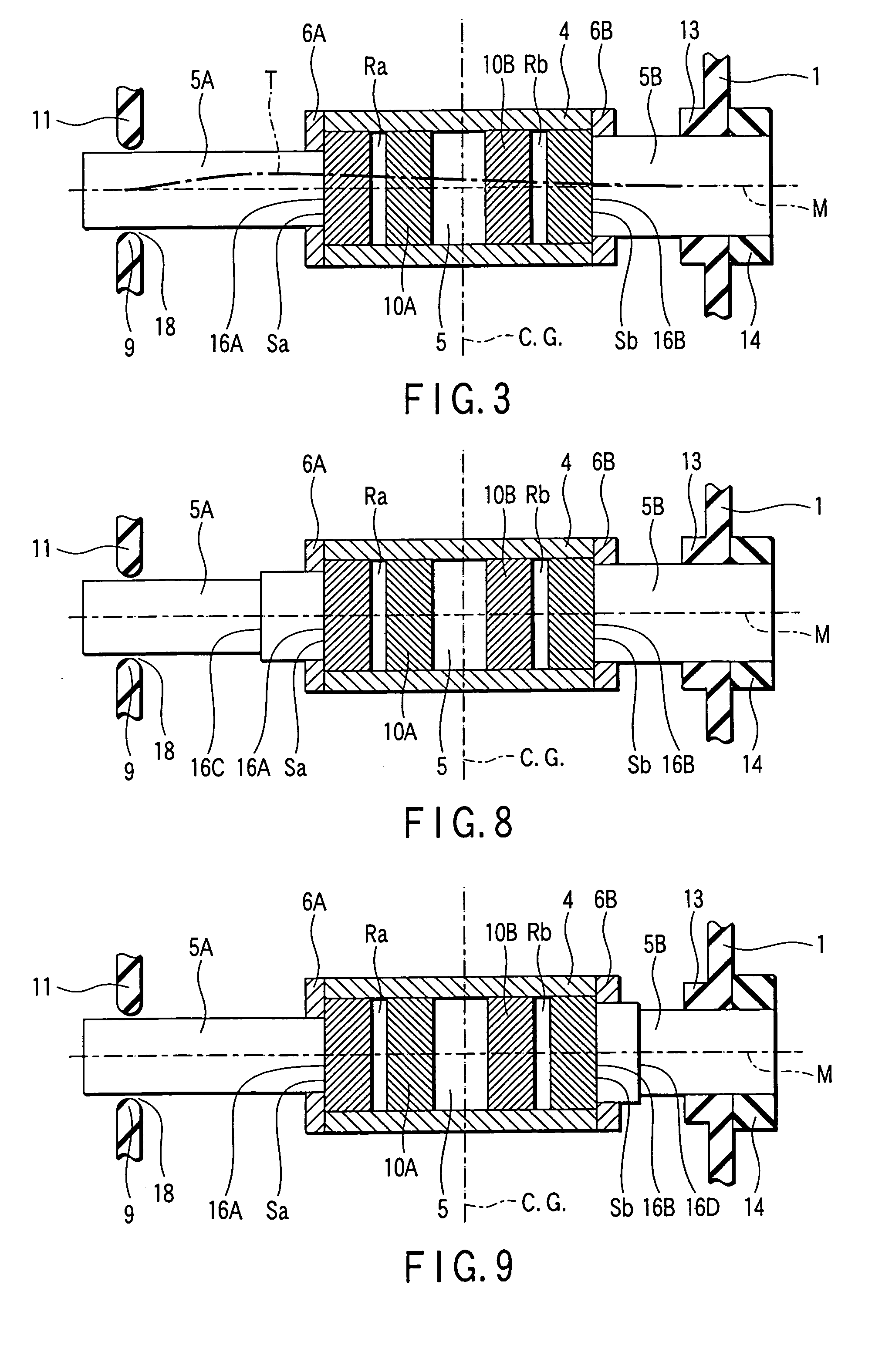
[0088]A rotary anode type X-ray tube according to the present invention will now be described with reference to FIG. 8.
[0089]FIG. 8 shows the rotary mechanism consisting of the radial bearings Ra, Rb, the thrust bearings Sa, Sb, the cylindrical portion 4, the stationary shaft 5, and the sections 5A, 5B of the stationary shaft 5, which are included in the rotary anode type X-ray tube shown in FIG. 1, and the supporting structure thereof. Those portions shown in FIG. 8 which correspond to the portions shown in FIG. 1 are denoted by the same reference numerals so as to avoid the overlapping description.
[0090]In the rotary anode type X-ray tube shown in FIG. 8, the first section 5A is formed of several portions differing from each other in the value of the bending rigidity. In the example shown in FIG. 8, the first section 5A is formed such that first and second shafts differing from each other in the diameter are joined to each other in a manner to form a stepped portion. However, the ...
third embodiment
[0094]A rotary anode type X-ray tube according to the present invention will now be described with reference to FIG. 9. Specifically, FIG. 9 shows the rotary mechanism included in the rotary anode type X-ray tube and the supporting structure thereof like FIG. 8. Those portions shown in FIG. 9 which correspond to the portions shown in FIG. 1 are denoted by the same reference numerals so as to avoid the overlapping description.
[0095]In the structure shown in FIG. 9, the first section 5A which is supported with tilting capability has a uniform bending rigidity over the entire region. On the other hand, the second section 5B that is supported stationary is formed of several portions differing from each other in the value of the bending rigidity. In the example shown in FIG. 9, the second section 5B includes first and second shaft portions that are joined to each other in a manner to form a stepped portion. However, the construction of the second section 5B is not limited to that shown i...
PUM
 Abstract
Description
Claims
Application Information
 - R&D
- Intellectual Property
- Life Sciences
- Materials
- Tech Scout
- Unparalleled Data Quality
- Higher Quality Content
- 60% Fewer Hallucinations
Browse by: Latest US Patents, China's latest patents, Technical Efficacy Thesaurus, Application Domain, Technology Topic, Popular Technical Reports.
© 2025 PatSnap. All rights reserved.Legal|Privacy policy|Modern Slavery Act Transparency Statement|Sitemap|About US| Contact US: help@patsnap.com


