
Light pipe optical coupling utilizing convex-shaped light pipe end

Inactive Publication Date: 2007-05-08
IBM CORP
View PDF9 Cites 67 Cited by
  • Summary
  • Abstract
  • Description
  • Claims
  • Application Information

AI Technical Summary

Benefits of technology

[0013]FIG. 2B is an elevational view of the light pipe of FIG. 2A, shown with a light-emitting component disposed within the recess in the one end thereof,

Problems solved by technology

These solutions are expensive, however, due to the fragility and difficulty of handling glass or other crystalline materials.
However, this solution also results in significantly increased costs.

Method used


Image

  • Light pipe optical coupling utilizing convex-shaped light pipe end
  • Light pipe optical coupling utilizing convex-shaped light pipe end
  • Light pipe optical coupling utilizing convex-shaped light pipe end

Examples


Embodiment Construction

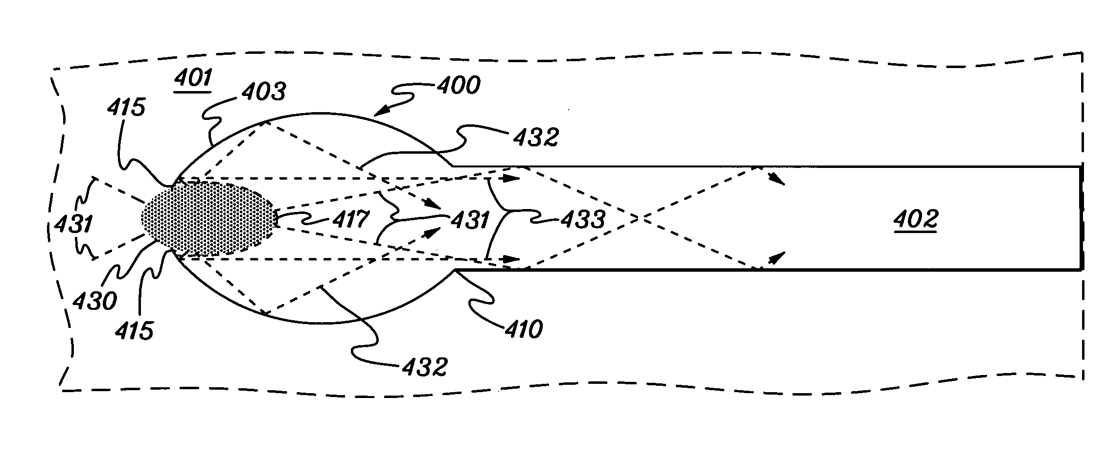
[0023]Generally stated, presented herein are various light transmission devices wherein a convex-shaped surface or extension is provided at the objective end of a light pipe, with a concave recess therein for at least partially accommodating a light source to facilitate capture of light into the light pipe, and thereby allow operation of the light transmission device over a longer distance than previously realizable. As used herein, the terms “light source” and “light-emitting component” are used interchangeably to refer to any light source structure. By way of example, the light source may be a light-emitting diode (LED) on an electronics board, such as a circuit card or printed circuit board. The convex-shaped extension is, in one embodiment, fabricated of a common material as the light pipe (e.g., a plastic) to have a common index of refraction. Further, the convex-shaped extension may be integrally molded with the light pipe.

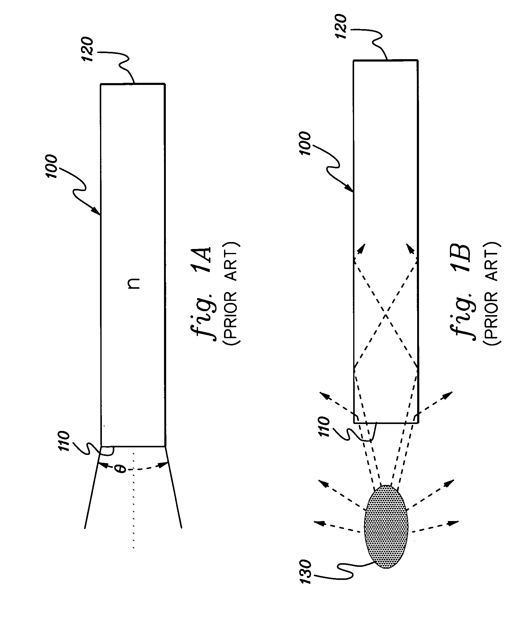
[0024]FIGS. 1A & 1B depict a conventional light pipe 1...


PUM


Abstract

A light transmission device is provided including a light pipe having two ends, one end being an ellipsoidal-shaped end. A recess is configured within the ellipsoidal-shaped end for reception of a light source that transmits light into the light pipe. The recess includes an interior concave wall, and the light source is at least partially received in the recess to face the interior concave wall via which light is transmitted into the light pipe. The ellipsoidal-shaped end further includes a curved surface configured to facilitate collection of light into the light pipe when the light source is at least partially received in the recess in the ellipsoidal-shaped end. The ellipsoidal-shaped end includes a first focal point and a second focal point, wherein the recess in the ellipsoidal-shaped end intersects the first focal point, and the second focal point is disposed adjacent to or within the light pipe.

Description

TECHNICAL FIELD[0001]This invention relates generally to light transmission devices and methods, and more particularly, to enhanced optical coupling of light sources to light pipes employing a convex-shaped light pipe end.BACKGROUND OF THE INVENTION[0002]Light pipe technology is a robust and inexpensive method for bringing light to the exterior of products for the purposes of communicating device status, or other important information to a user. Generally, a light pipe is used in situations where physical restrictions (e.g., lack of space, high component density), safety concerns (such as component accessibility to the end user, fragile bulbs, heat buildup), or other factors prevent the light-emitting component from being mounted in a way that provides direct visibility. Light pipes are often rendered as round-cross-section or rectangular-cross-section clear plastic structures, where the objective end is placed flush with, or close to, the light-emitting component. The viewed end is...

Claims


Application Information

Patent Timeline
IPC IPC(8): G02B6/00
CPCG02B6/00G02B6/4298
Inventor ARENELLA, KENNETHBARRINGER, DENNIS R.DECUSATIS, CASIMER M.QUALTERS, KEVIN R.SHADOFF, KENNETH A.
Owner IBM CORP
Features
  • Generate Ideas
  • Intellectual Property
  • Life Sciences
  • Materials
  • Tech Scout
  • Unparalleled Data Quality
  • Higher Quality Content
  • 60% Fewer Hallucinations
Learn More