Image forming apparatus and method of detecting the detection characteristics of a reflection density sensor

a technology of reflection density and image forming apparatus, which is applied in the direction of electrographic process apparatus, instruments, optics, etc., can solve the problems of increasing the required amount of mounting space and the number of parts, deteriorating the detection characteristics of optical reflection density sensors in actual use, and difficult to apply this method to a small inexpensive image forming apparatus

Inactive Publication Date: 2007-05-08
RICOH PRINTING SYST
View PDF4 Cites 19 Cited by
  • Summary
  • Abstract
  • Description
  • Claims
  • Application Information

AI Technical Summary

Benefits of technology

[0016]In accordance with this invention, a test-pattern toner image for detection (calibration) of the detection output characteristics of an optical reflection density sensor is produced by superimposing toner images that have been developed by a plurality of developers into an image formed of multiple toner image layers. With this, the image forming apparatus of this invention can obtain toner images having the required quantity of toner. Therefore, this invention can provide a method for detecting the detection characteristics of an optical reflection density sensor that is suitably applicable to a small and inexpensive image forming apparatus and an image forming apparatus using this detection characteristics detecting method.

Problems solved by technology

However, the detection characteristics of the optical reflection density sensor in actual use tend to deteriorate because of time-lapse deterioration of the light emitting diode (LED) that is used as is a light source for illuminating the test pattern and the light receiving photo diode (PD) that is used as a detection element and because of time-lapse contamination of the optical system.
This increases the required amount of mounting space and the number of parts.
Therefore, it is hard to apply this method to a small inexpensive image forming apparatus.
Further, the method which uses a high-density test pattern toner image cannot detect such a high-density test pattern toner image when the high-density test pattern toner image cannot be formed by increasing the developing bias.
This decreases the control precision.
As one of the reasons why a high-density test pattern image cannot be formed, we can assume that this is due to deterioration of the developing ability of the developers that form the test pattern toner image.

Method used


Image

  • Image forming apparatus and method of detecting the detection characteristics of a reflection density sensor
  • Image forming apparatus and method of detecting the detection characteristics of a reflection density sensor
  • Image forming apparatus and method of detecting the detection characteristics of a reflection density sensor

Examples


embodiment 1

[0026][Embodiment 1]

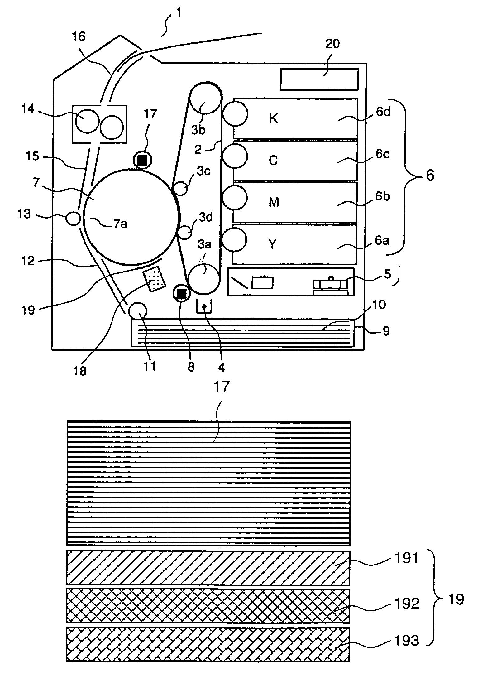
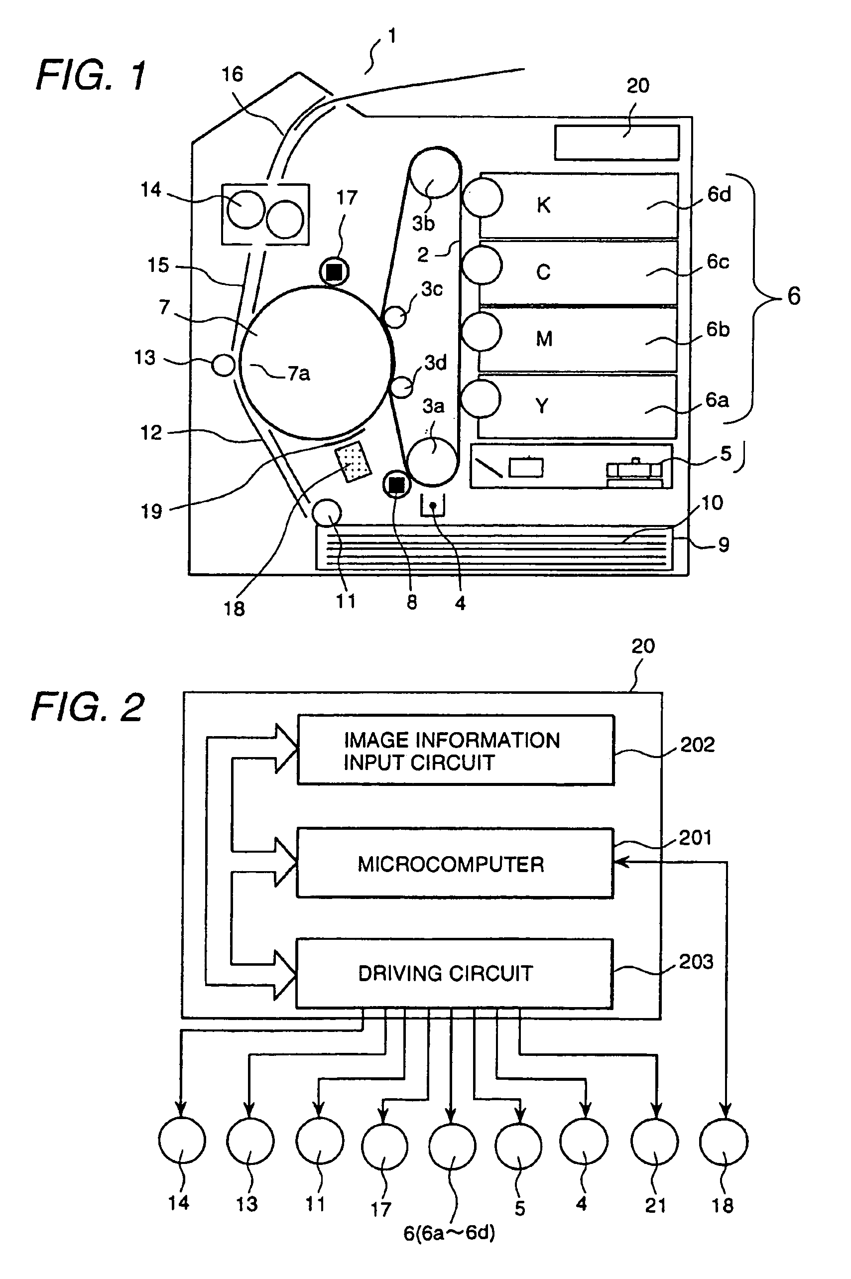
[0027]FIG. 1 is a diagrammatic sectional view of an image forming apparatus representing the first embodiment of this invention. This image forming apparatus is configured to transfer a plurality of toner images from an endless photosensitive belt onto the surface of an intermediate transfer drum in a superposition mode to record a single color image.

[0028]In FIG. 1, the image forming apparatus 1 is configured as explained below. In the internal side of the endless photosensitive belt 2, which is provided to form toner images of each color, a plurality of guide rollers (3a to 3d) engage with the belt and allow the belt to move over a predetermined path. On the outer side of the endless photosensitive belt 2, there are a charger 4 which operates to charge the belt surface evenly; a laser exposure unit 5 which operates to apply laser light to the charged surface of the endless photosensitive belt 2 so as to form electrostatic latent images, such as recording images...

embodiment 2

[0063][Embodiment 2]

[0064]FIG. 6 is a diagrammatic sectional view of an image forming apparatus representing a second embodiment of this invention. This image forming apparatus is configured to record a multi-color image by transferring toner images of multiple colors respectively formed by four photosensitive drums onto an intermediate transfer belt in a superimposed manner.

[0065]The image forming apparatus 1 of FIG. 6 is configured as follows. Embodiment 2 is basically the same as Embodiment 1 of FIG. 1, but Embodiment 2 uses a drum for each photosensitive developer, instead of the photosensitive endless belt, and it also uses an intermediate transfer belt instead of an intermediate transfer drum.

[0066]In other words, the image forming apparatus 1 has a plurality of photosensitive drums 2a to 2d. Each photosensitive drum (2a to 2d) has a charger (4a to 4d) that evenly charges the surface of the respective photosensitive drum, a laser exposure unit (5a to 5d) that exposes the evenl...

embodiment 3

[0074][Embodiment 3]

[0075]FIG. 7 is a diagrammatic sectional view of an image forming apparatus representing a third embodiment of this invention. This image forming apparatus forms and superimposes each toner image of a different color into a single multi-color toner image on the endless photosensitive belt 2 and transfers the resulting multi-color toner image onto a recording sheet.

[0076]The image forming apparatus 1 of FIG. 7 is almost the same as that of FIG. 6, but this embodiment forms each toner image of a different color by means of respective developers 6a to 6d, superimposes them into a single multicolor toner image on the photosensitive belt 7, and transfers the resulting multi-color toner image onto a recording sheet without using an intermediate transfer belt 7. As shown in FIG. 7, the endless belt 2 is tensioned by guide roller 23a–23c, and is also rotated by guide rollers 23a–23c. This configuration without an intermediate transfer belt or drum provides for a reductio...


PUM


Abstract

An image forming apparatus is able to form steady test-pattern toner images for calibration of reflection density detection characteristics with ample toner. The operation consists of forming a test-pattern toner image for calibration of the reflection density detection characteristics, which is formed of a plurality of toner images of different colors aside from a reference test-pattern toner image for controlling image forming conditions, detecting the detection characteristics of a reflection density sensor from the result of detection of the quantity of toner attached to the test-pattern toner image for calibration of the reflection density detection characteristics, and calibrating the output characteristics of the reflection density sensor.

Description

BACKGROUND OF THE INVENTION[0001]This invention relates to an image forming apparatus, such as a printer, facsimile, copier, and the like, that forms images by use of an electrophotographic method to develop electrostatic latent images with colored particles (toner), and to a method for detecting the detection characteristics of an optical reflection density sensor which is used in the image forming apparatus.[0002]In the electrophotographic image forming field of copiers and laser printers, to stabilize the supply of toner to developers (replacement of developers) and the formation of images, the image forming apparatus forms a reference test pattern for controlling the image forming conditions on a photosensitive element or an intermediate transfer element under a preset operating condition, detects the quantity of toner on the test pattern, controls the supply of toner to the developer or the image forming condition (such as the charging potential, the exposure intensity, and the...

Claims


Application Information

Patent Timeline
Patent Type & Authority Patents(United States)
IPC IPC(8): G03G15/00G03G21/00
CPCG03G15/0131G03G15/5058G03G2215/00042G03G2215/00059G03G2215/00063G03G2215/0161
Inventor YAMADA, SHINTAROSHIMADA, AKIRASATO, TATSUNARIFUKASAWA, NOBUAKINARITA, SATOSHI
Owner RICOH PRINTING SYST
Why Eureka
Try Eureka