

False pin soldering test device and method
A technology for testing pins and virtual soldering, applied in the field of testing, can solve the problems of high cost of testing equipment, complicated operation and testing process, etc., achieve the effect of convenient support means, and solve the effect of complicated operation and testing process
- Summary
- Abstract
- Description
- Claims
- Application Information
AI Technical Summary
Problems solved by technology
Method used
Image

Examples
example 1
[0062] Example 1: Use D3 and D4, and judge whether there is a virtual weld through the voltage value.
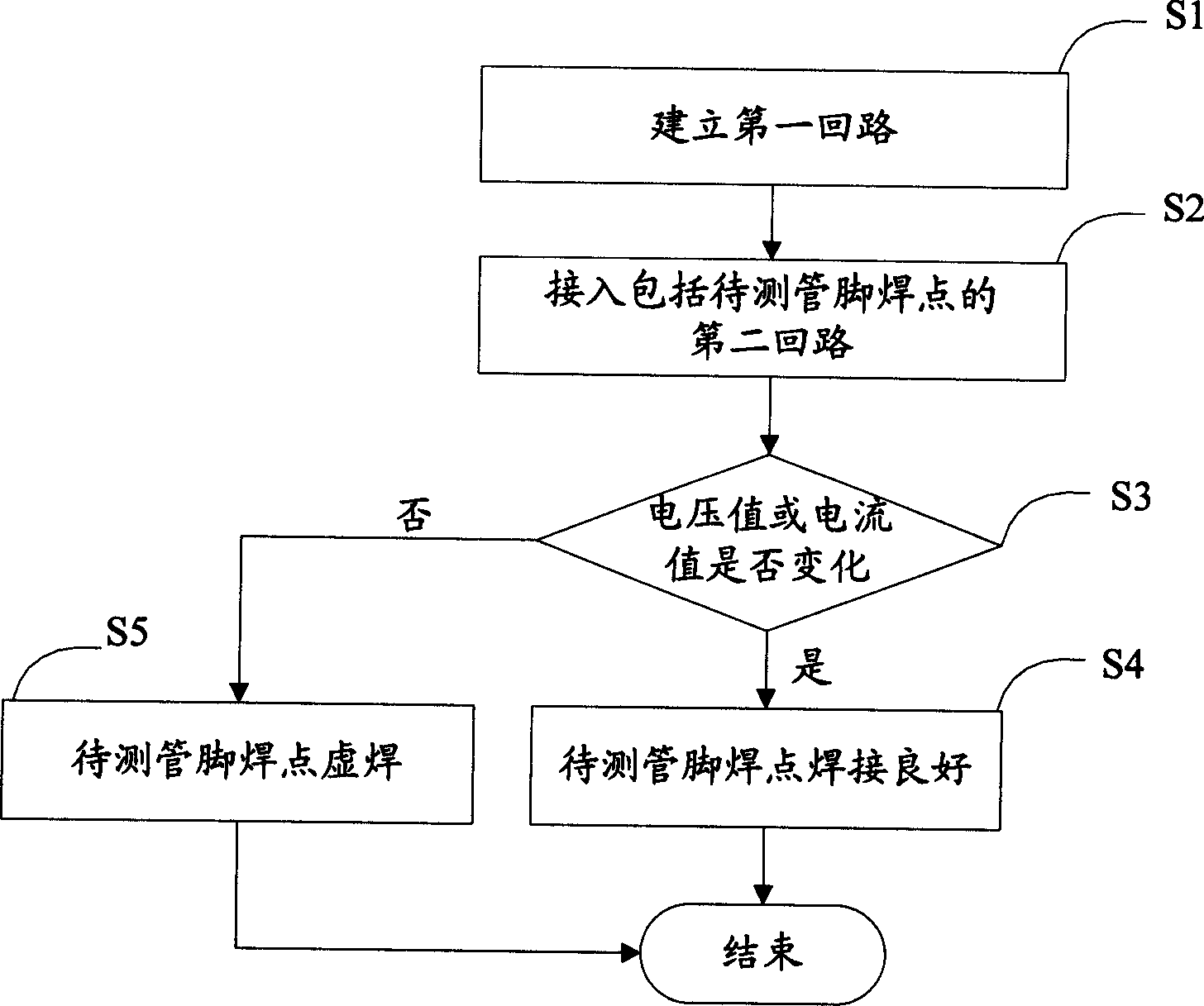
[0063] S101. Establish a first loop.
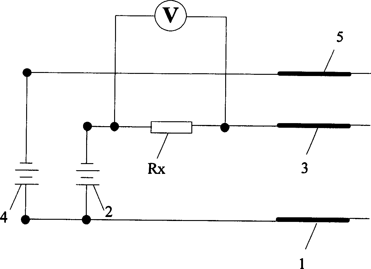
[0064] Connect the ground probe 1 and the reference probe 3 at both ends of the first open circuit in the voltmeter device to the selected reference ground 11 and the PCB trace where the reference pin 31 or its solder joint is located to form the first One circuit. see Figure 5 As shown, the first power supply 2, the reference resistor Rx, the protection diode D3 and the equivalent resistor R2 are connected in series in the first loop. Here, the first power supply 2 should select a negative voltage, so that the protection diode D3 is turned on.
[0065] In this way, the voltmeter connected in parallel with the reference resistor Rx will display the reference voltage value.
[0066] S102. Connect to the second circuit including the solder joint of the pin to be tested.
[0067] see Image 6 As shown, on the premise of maintaining ...
example 2
[0074] Example 2: Use D3 and D4, and judge whether there is a virtual weld by the current value.
[0075] S201. Establish a first loop.
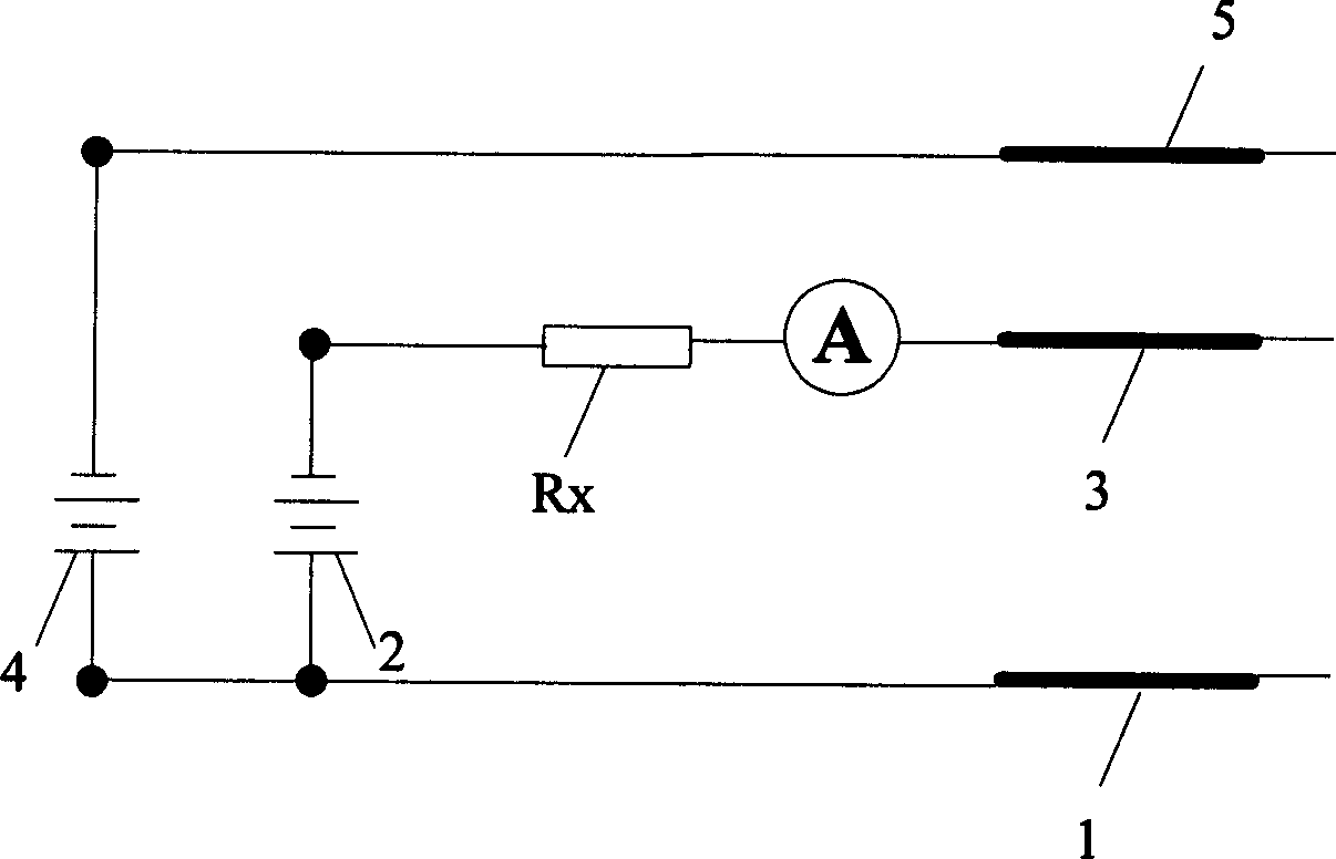
[0076] Connect the above-mentioned ground probe 1 and reference probe 3 at both ends of the first open circuit in the ammeter device to the selected reference ground 11 and the PCB trace where the reference pin 31 or its solder joint is located to form a first circuit. see Figure 7 As shown, a first power supply 2 , a reference resistor Rx, an ammeter, a protection diode D3 and an equivalent resistor R2 are connected in series in the first loop. Here, the first power supply 2 should select a negative voltage, so that the protection diode D3 is turned on.
[0077] In this way, the ammeter connected in series with the reference resistor Rx will display the reference current value.
[0078] S202. Connect to the second loop including the solder joint of the pin to be tested.
[0079] see Figure 8 As shown, on the premise of maintaining t...
example 3
[0086] Example 3: Use D1 and D2, and judge whether there is a virtual weld through the voltage value.
[0087] S301. Establish a first loop.
[0088] Connect the ground probe 1 and the reference probe 3 at both ends of the first open circuit in the voltmeter device to the selected reference ground 12 and the PCB trace where the reference pin 31 or its solder joint is located to form the first One circuit. A first power supply 2 , a reference resistor Rx, a protection diode D1 and an equivalent resistor R2 are connected in series in the first loop. Here, the first power supply 2 should select a forward voltage so that the protection diode D1 is turned on.
[0089] In this way, the voltmeter connected in parallel with the reference resistor Rx will display the reference voltage value.
[0090] S302. Connect to the second loop including the solder joint of the pin to be tested.
[0091] On the premise of maintaining the above-mentioned first loop, connect the 5 points of the ...
PUM
 Abstract
Description
Claims
Application Information