
Image forming apparatus having subsidiary charge roller

a technology of image forming apparatus and charge roller, which is applied in the direction of electrographic process apparatus, instruments, corona discharge, etc., can solve the problems of deteriorating image quality and reducing the life of the developer, and achieve the effect of preventing deterioration of image quality

Inactive Publication Date: 2007-05-08
S PRINTING SOLUTION CO LTD
View PDF13 Cites 8 Cited by
  • Summary
  • Abstract
  • Description
  • Claims
  • Application Information

AI Technical Summary

Benefits of technology

"The present invention provides an image forming apparatus with a subsidiary charge roller that can prevent uneven charge, contamination of the surface, and decrease in image density under specific environments. The line pressure of the subsidiary charge roller against the development roller is maintained within a predetermined range to prevent deterioration of image quality due to uneven charge and increased stress of the developer. The diameter ratio of the subsidiary charge roller to the development roller is maintained within a predetermined range to prevent uneven charge and scattering of developer. The linear velocity ratio of the subsidiary charge roller to the development roller is maintained within a predetermined range to prevent deterioration of image quality due to increased stress of the developer. The surface roughness of the subsidiary charge roller is maintained within a predetermined range to prevent uneven charge and contamination of the developer layer. The amount of nip between the development roller and the subsidiary charge roller is maintained within a predetermined range to prevent uneven charge and improve image quality."

Problems solved by technology

For example, these environments can include a low-temperature and low-humidity environment, and a high-temperature environment, which serve to decrease the life-span of the developer and deteriorate image quality due to increased stress of the developer.

Method used


Image

  • Image forming apparatus having subsidiary charge roller
  • Image forming apparatus having subsidiary charge roller
  • Image forming apparatus having subsidiary charge roller

Examples


Embodiment Construction

[0069]Hereinbelow, exemplary embodiments of the present invention will be described in greater detail with reference to the accompanying drawings. In the following description, like parts to those of the devices described above will be indicated with like reference numerals.

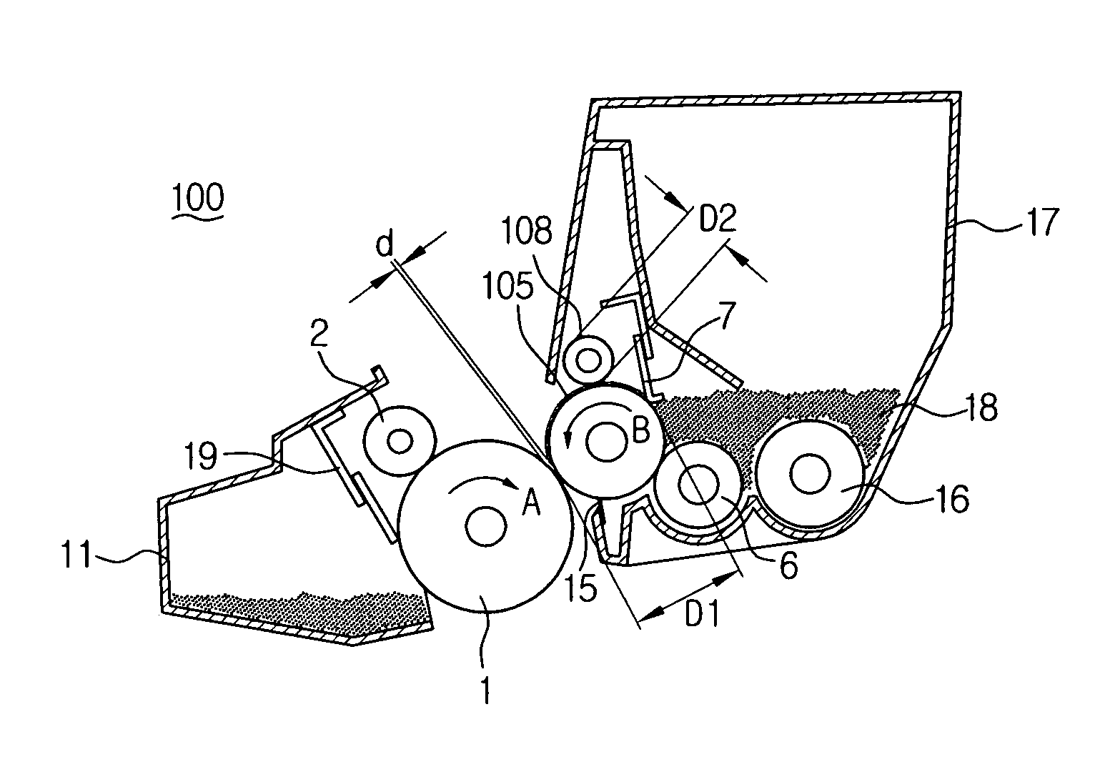
[0070]FIG. 4 shows a development unit 100 of an image forming apparatus according to an exemplary embodiment of the present invention in which, a subsidiary charge roller is incorporated.

[0071]The development unit 100 comprises a development roller 105 spaced from a photosensitive conductor 1 by a predetermined gap d, and a developer supply roller 6 for supplying developer 18 containing nonmagnetic one-component toner, wherein the developer supply roller 6 is positioned adjacent to the development roller 105 and is rotating in a same direction with the development roller 105 as indicated by arrow B in FIG. 1. The unit also includes a stirring roller 16 for stirring developer stored in a developer bin 17, and a de...


PUM


Abstract

An image forming apparatus including a subsidiary charge roller and a development roller, wherein the diameter ratio I of the subsidiary charge roller to the development roller is in the range of 0.45 to 0.8. The subsidiary charge roller and the development roller can be arranged such that the linear velocity of the subsidiary charge roller Vs is larger than the linear velocity of the development roller Vd, and preferably the linear velocity ratio K of the subsidiary charge roller to the development roller is in the range of 1.01 to 1.06. Alternatively, the image forming apparatus can further include a compression section for applying a predetermined pressure to the opposite ends of the shaft of the subsidiary roller and a development roller gear coaxially formed on the development roller shaft.

Description

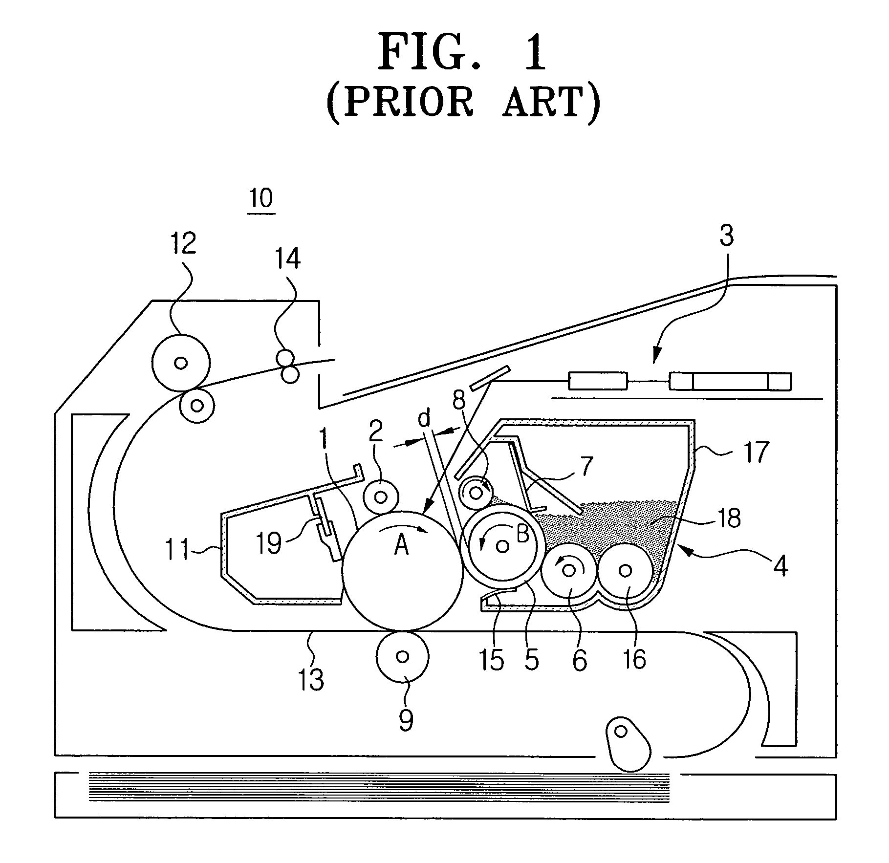
CROSS-REFERENCE TO RELATED APPLICATIONS[0001]This application claims the benefit under 35 U.S.C. §119(a) of Korean Patent Application No. 2003-99099 entitled “Image Forming Apparatus Having Subsidiary Charge Roller”, filed in the Korean Intellectual Property Office on Dec. 29, 2003, the entire contents of which are incorporated herein by reference.BACKGROUND OF THE INVENTION[0002]1. Field of the Invention[0003]The present invention relates to an electrophotographic image forming apparatus such as a copying machine, a facsimile apparatus, and a laser printer. More particularly, the present invention relates to an image forming apparatus having a subsidiary charge roller which allows developer attached to a development roller to be evenly charged.[0004]2. Description of the Related Art[0005]In general, an electrophotographic image forming apparatus such as a laser beam printer, copying machine and facsimile apparatus, obtains a permanent image formed by the steps of first contacting d...

Claims


Application Information

Patent Timeline
Patent Type & Authority Patents(United States)
IPC IPC(8): G03G15/08G03G15/02
CPCG03G15/0812G03G15/02
Inventor KIM, YOUNG-MINAHN, BYUNG-SUNPARK, SANG-CHEOL
Owner S PRINTING SOLUTION CO LTD
Learn More