Apparatus for intraoperative neural monitoring

a neural monitoring and apparatus technology, applied in artificial respiration, therapy, application, etc., can solve the problems of not providing an early indication of spinal cord dysfunction, unable to identify more subtle spinal cord impairment, and limited wake-up testing to evaluate gross motor function

Active Publication Date: 2007-05-08
MEDTRONIC XOMED INC
View PDF10 Cites 245 Cited by
  • Summary
  • Abstract
  • Description
  • Claims
  • Application Information

AI Technical Summary

Problems solved by technology

Spinal cord monitoring has traditionally relied on the Stagnara wake-up test, which is ordinarily performed at the conclusion of a surgical procedure and thusly does not provide an early indication of spinal cord dysfunction.
Wake-up testing is limited to evaluating gross motor function and fails to identify more subtle spinal cord impairments.
Oftentimes administration of the wake-up test is compromised by anesthetic influences.
Additional disadvantages of the wake-up test include the risks of air embolism and self-extubation.
However, it is possible for motor deficits to develop intraoperatively despite the lack of medically significant changes in recorded SEPs, i.e. false negatives.
In addition, in some patients it may be difficult or not possible to obtain SEP readings intraoperatively.
Being low amplitude, SEP responses require averaging over time such that the readings obtained from SEPs are not as close to real-time as would be desirable.
Routine intraoperative spinal cord monitoring using SEPs cannot effectively spatially resolve the loss of certain nerve roots, such as the lumbosacral root, which optimally requires electromyographic (EMG) responses from muscles enervated by the nerve roots.
Nerve irritation or injury may occur and remain undetected even while standard MEP testing appears normal.
Prior intraoperative neural monitoring systems are either not designed to provide electrical current of sufficient magnitude to elicit MEPs or are not designed to provide automatic biphasic electrical stimulation sequences between the stimulating electrodes.
However, where the direction or polarity of current flow between the stimulating electrodes is fixed, providing monophasic electrical stimulation in one direction or polarity between the stimulating electrodes, the anatomical areas cannot be sequentially alternatingly stimulated without manually reversing the locations of the stimulating electrodes with respect to the anatomical areas or electromechanically reversing the lead polarities for the stimulating electrodes each time polarity or direction of current flow between the stimulating electrodes is to be reversed.
Prior intraoperative neural monitoring systems used to elicit MEPs and / or the stimulators used to elicit MEPs are therefore associated with various disadvantages including additional operational steps which increase the duration of the surgical procedures to the detriment of patients and medical personnel, increased complexity and confusion attendant with intraoperative neural monitoring, the possible occurrence of false negative responses due to stimulation on the wrong side of the body, and the need for greater human and / or mechanical intervention.
Prior intraoperative neural monitoring systems used to elicit MEPs and / or the stimulators used to elicit MEPs have further drawbacks including failing to provide both positive and negative monophasic and automatic biphasic sequenced outputs from a single stimulator, failing to present left and right EMG waveforms simultaneously and correlated in time to biphasic electrical stimulation to allow a more complete interpretation of neurological motor responses, and the inability to efficiently integrate multiple neural monitoring modalities.

Method used


Image

  • Apparatus for intraoperative neural monitoring
  • Apparatus for intraoperative neural monitoring
  • Apparatus for intraoperative neural monitoring

Examples


Embodiment Construction

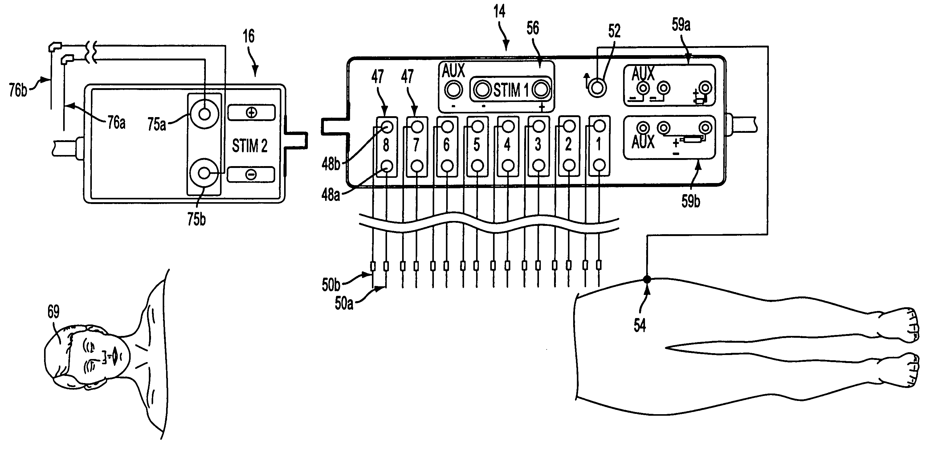
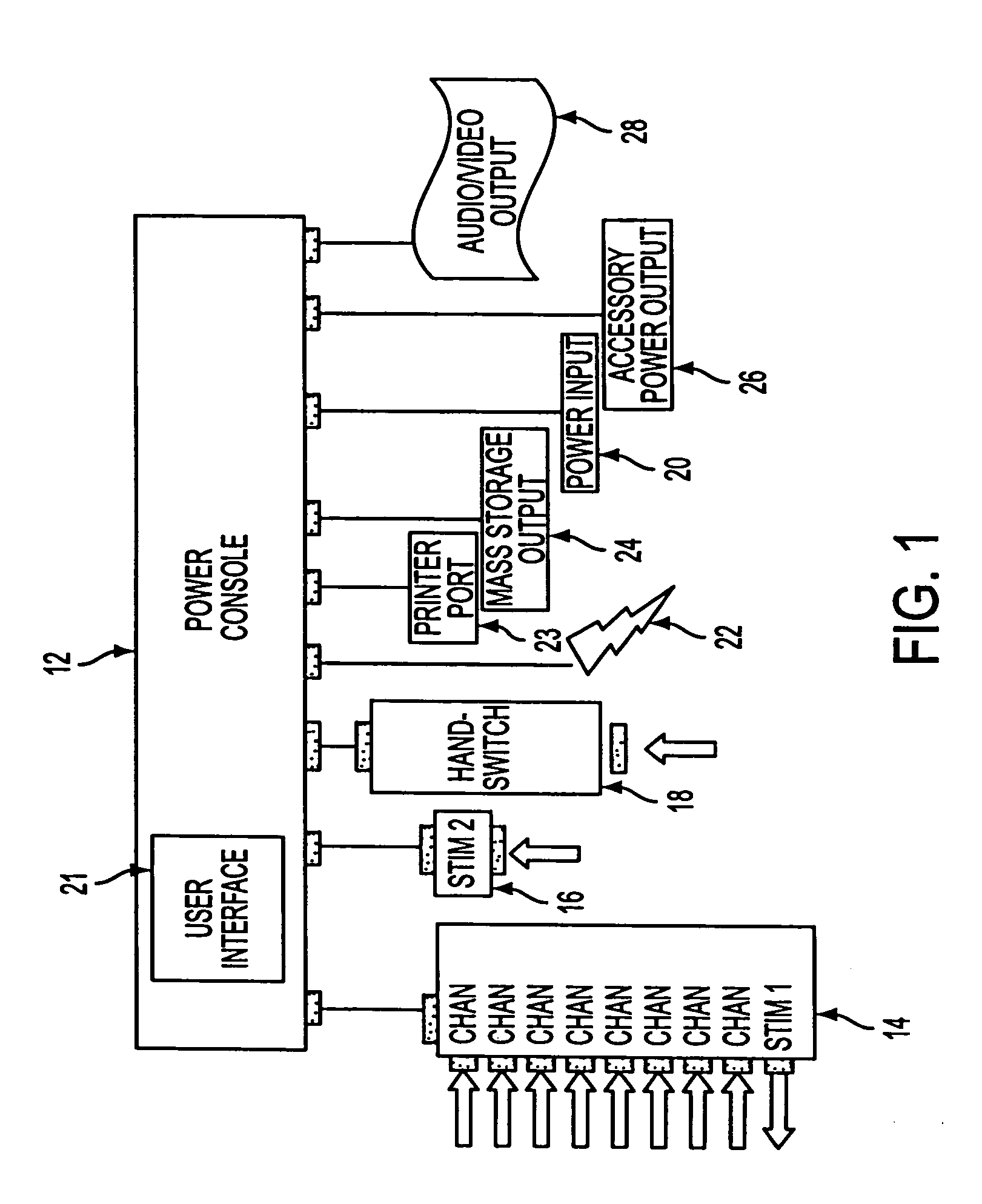
[0054]An intraoperative neural monitoring system 10 according to the present invention is depicted in FIG. 1 and comprises a power console 12, a patient interface unit 14 for being electrically connected with the power console to deliver Stim 1 electrical stimulation, a stimulator 16 for being electrically connected with the power console to deliver Stim 2 electrical stimulation, a hand switch 18 for controlling activation of Stim 2 electrical stimulation, and a power input 20 for supplying electric power to the power console from a suitable power source. The power console 12 includes a user interface 21 providing multilingual (voice and text) interaction with a user, and preferably the power console includes one or more connectors for connection with one or more muting detectors 22. The power console 12 may include a printer port 23, a mass storage output 24, an accessory power output 26 and / or an audio / video output 28 as explained further below.

[0055]The power console 12 is shown ...


PUM


Abstract

An intraoperative neural monitoring system includes a power source and a simulator powered by the power source to deliver a cycle of electrical stimulation to a patient as a first group of positive or negative phase pulses automatically followed by a second group of pulses of opposite phase or polarity to the pulses of the first group. An activation performed to initiate delivery of the first group of pulses is effective to deliver the entire cycle of stimulation. A method of intraoperative neural monitoring involves activating a simulator to deliver a biphasic cycle of electrical stimulation to a patient during an operative procedure, delivering the entire cycle of electrical stimulation to the patient in response to the activating step and detecting EMG activity in the patient.

Description

CROSS-REFERENCE TO RELATED PATENT APPLICATION[0001]This application claims priority from prior provisional patent application Ser. No. 60 / 441,471 filed Jan. 22, 2003, the entire disclosure of which is incorporated herein by reference.BACKGROUND OF THE INVENTION[0002]1. Field of the Invention[0003]The present invention relates generally to intraoperative neural monitoring and, more particularly, to apparatus and methods for intraoperative neural monitoring involving monitoring of the spinal cord using motor evoked potentials elicited by electrical stimulation.[0004]2. Brief Discussion of the Related Art[0005]Intraoperative neural monitoring involving intraoperative monitoring of the spinal cord has become accepted as an effective means to avoid neural deficits in patients undergoing various types of surgical procedures in which the spinal cord is at risk of injury. By monitoring the integrity of the spinal cord motor tracts during surgery, impairments in motor function may be detecte...

Claims


Application Information

Patent Timeline
Patent Type & Authority Patents(United States)
IPC IPC(8): A61N1/00A61B5/04A61B5/0488A61N1/36
CPCA61B5/04001A61B5/0488A61B5/4519A61N1/36014A61N1/36035A61B5/7217A61B5/4041A61B5/407A61N1/3604A61B5/24A61B5/389
Inventor HACKER, DAVID C.SKINNER, STANLEY A.TRANSFELDT, ENSOR E.STERRANTINO, PETER P.RUPP, LIONEL
Owner MEDTRONIC XOMED INC
Why Eureka
Try Eureka