
Apparatus and method for simultaneous usage of multiple die casting tools

a technology of die casting tools and die casting machines, which is applied in casting equipment, casting plants, manufacturing tools, etc., can solve the problems of inability to cost-effectively produce large production runs of identical parts, inability to cost-effectively produce small production runs of parts or production runs of multiple parts, and inability to cost-effectively produce both large and small production runs of parts. , to achieve the effect of cost-effective production of both large and small parts

Inactive Publication Date: 2007-05-15
GERARD HELLEBUSCH REVOCABLE TRUST DATED AUGUST 22 1996 +2
View PDF16 Cites 18 Cited by
  • Summary
  • Abstract
  • Description
  • Claims
  • Application Information

AI Technical Summary

Benefits of technology

[0006]Therefore, what is needed is a die-casting apparatus and method with faster cycle times that can cost-effectively produce both large and small runs of parts. Also, there is a need for a die-casting apparatus that can produce multiple parts during a single run.

Problems solved by technology

In addition, production runs using current designs are limited to using only one type of die at a time with each die producing the same part.
Therefore, only large production runs of identical parts can be produced cost-effectively.
In other words, it is not possible to cost-effectively produce either small production runs of parts or production runs of multiple parts.

Method used


Image

  • Apparatus and method for simultaneous usage of multiple die casting tools
  • Apparatus and method for simultaneous usage of multiple die casting tools
  • Apparatus and method for simultaneous usage of multiple die casting tools

Examples


Embodiment Construction

[0039]The following detailed description illustrates the invention by way of example and not by way of limitation. The description clearly enables one skilled in the art to make and use the invention, describes several embodiments, adaptations, variations, alternatives, and uses of the invention, including what is presently believed to be the best mode of carrying out the invention.

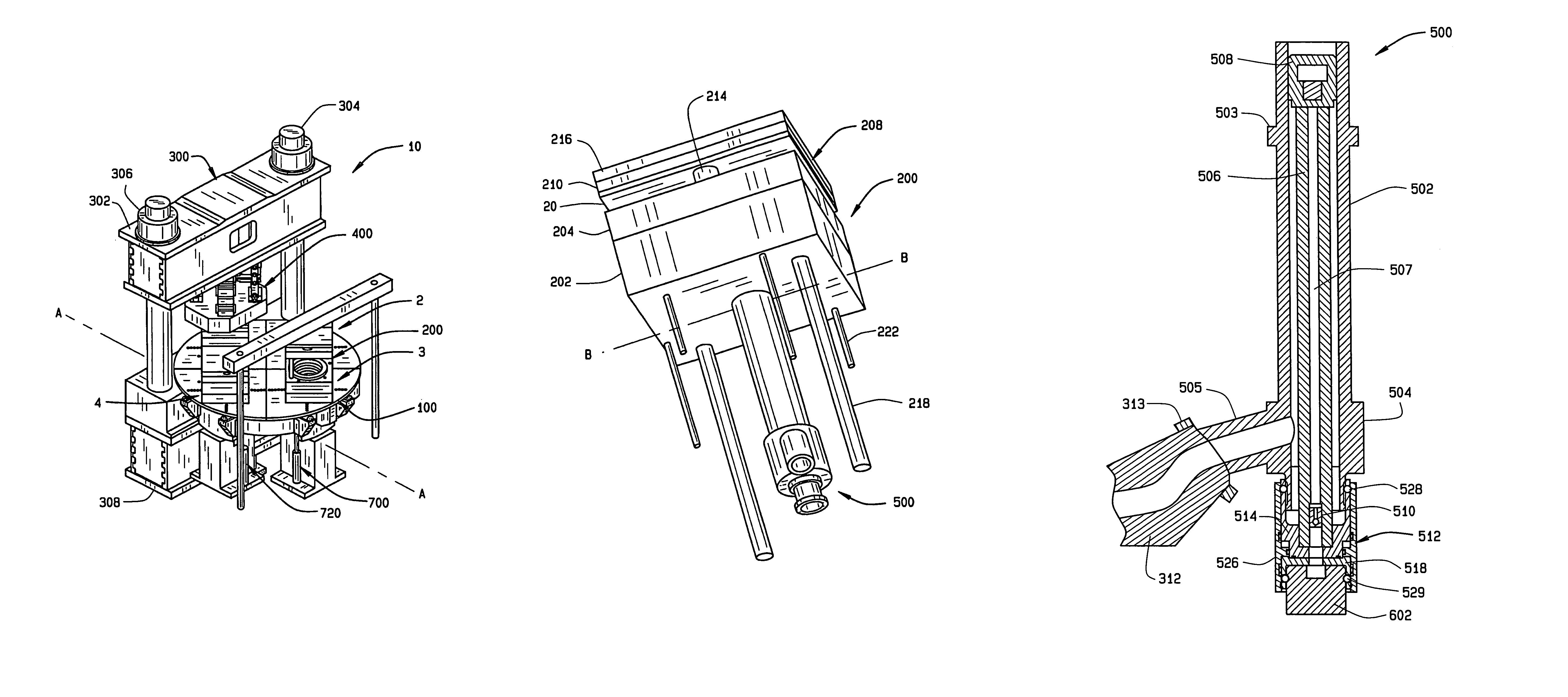
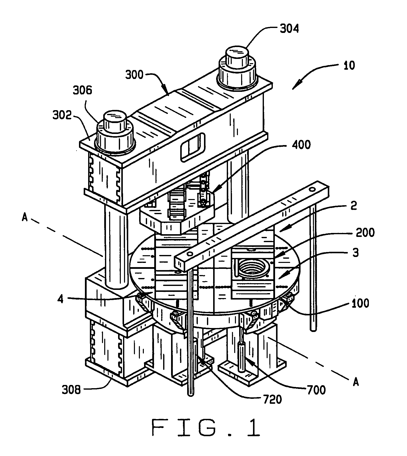
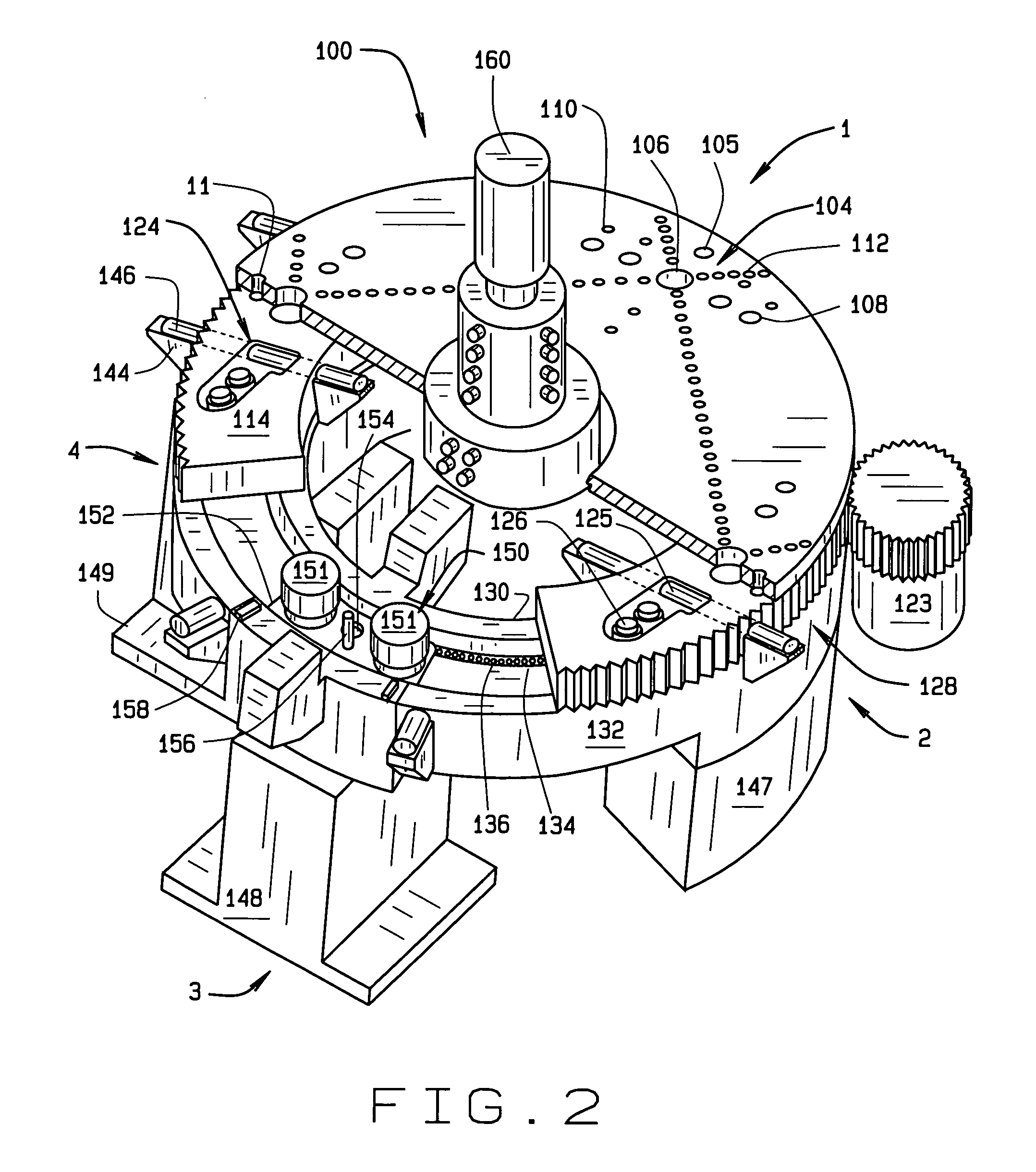
[0040]FIG. 1 illustrates a perspective view of an embodiment of a die-casting apparatus 10 of the present invention. The die-casting apparatus 10 divides the die-casting process into four stations: injection station 1, cooling station 2, ejection station 3, and recovery station 4. In general, at station 1 molten material is injected into a die block assembly 200. At station 2, the molten material cools and solidifies into a finished part. At station 3, the finished part is ejected from the die block assembly 200. Finally, at station 4 the die block assembly 200 is cleaned, lubricated, and cooled in prepar...


PUM

PropertyMeasurementUnit
pressureaaaaaaaaaa
sizeaaaaaaaaaa
speedaaaaaaaaaa

Abstract

The preferred embodiment of the present invention is a die casting apparatus and method evidencing increased apparatus output including the ability of using multiple die tools. The invention includes an indexing assembly removably engaged with at least one die block assembly for transporting between four stations, including an injection station, a cooling station, an ejection station, and a recovery station. The injection station includes a frame, a clamp assembly attached to the frame for clamping and releasing the die block assembly, a shot sleeve assembly engaged with the die block assembly for receiving molten material, such as metal, from a furnace means and injecting the molten material into the die block assembly, and a shot cylinder releasably coupled with the shot sleeve assembly for controlling the injection of molten material. The ejection station includes an ejector lift assembly which engages the die block assembly for ejecting a finished part from the die block assembly, and the recovery station includes an ejector drop assembly which engages the die block assembly for placing a preload on the die block assembly.

Description

CROSS-REFERENCE TO RELATED APPLICATIONS[0001]This application is related to U.S. Provisional Patent Application No. 60 / 618,056 filed Oct. 12, 2004 from which priority is claimed, and is hereby incorporated by reference.STATEMENT REGARDING FEDERALLY SPONSORED RESEARCH[0002]Not Applicable.BACKGROUND OF THE INVENTION[0003]The present invention relates to a die casting apparatus and method of use. More specifically, the present invention relates to die casting apparatus and method evidencing increased apparatus output including the ability of using multiple die tools. While the invention is described in particular with respect to die casting, those skilled in the art will recognize the wider applicability of the inventive concepts set forth hereinafter[0004]Die-casting is a popular manufacturing process because of its ability to cost-effectively produce complex parts while maintaining tight tolerances. Generally, the die-casting process begins by melting an appropriate material, such as...

Claims


Application Information

Patent Timeline
Patent Type & Authority Patents(United States)
IPC IPC(8): B22D17/12
CPCB22D17/2023B22D17/2236B22D17/32
Inventor GRAVES, DAVE L.HELLEBUSCH, GERARD M.MEYER, PATRICK ROBERTYEGGE, SR., JOHN A.RIO, TODD
Owner GERARD HELLEBUSCH REVOCABLE TRUST DATED AUGUST 22 1996
Learn More