Torque-applying tool and torque controller therefor

Active Publication Date: 2014-04-03
STANLEY WORKS THE
View PDF12 Cites 12 Cited by
  • Summary
  • Abstract
  • Description
  • Claims
  • Application Information

AI Technical Summary

Benefits of technology

[0007]There is a need in the art for a tool torque controller

Problems solved by technology

However, in view of the high speed of the tool, oversho

Method used


Image

  • Torque-applying tool and torque controller therefor
  • Torque-applying tool and torque controller therefor
  • Torque-applying tool and torque controller therefor

Examples


Embodiment Construction

[0007]There is a need in the art for a tool torque controller that reduces cycle time without compromising torque accuracy.

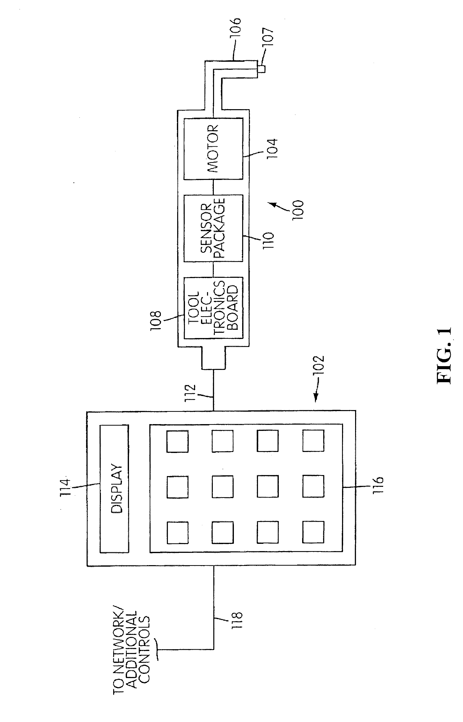
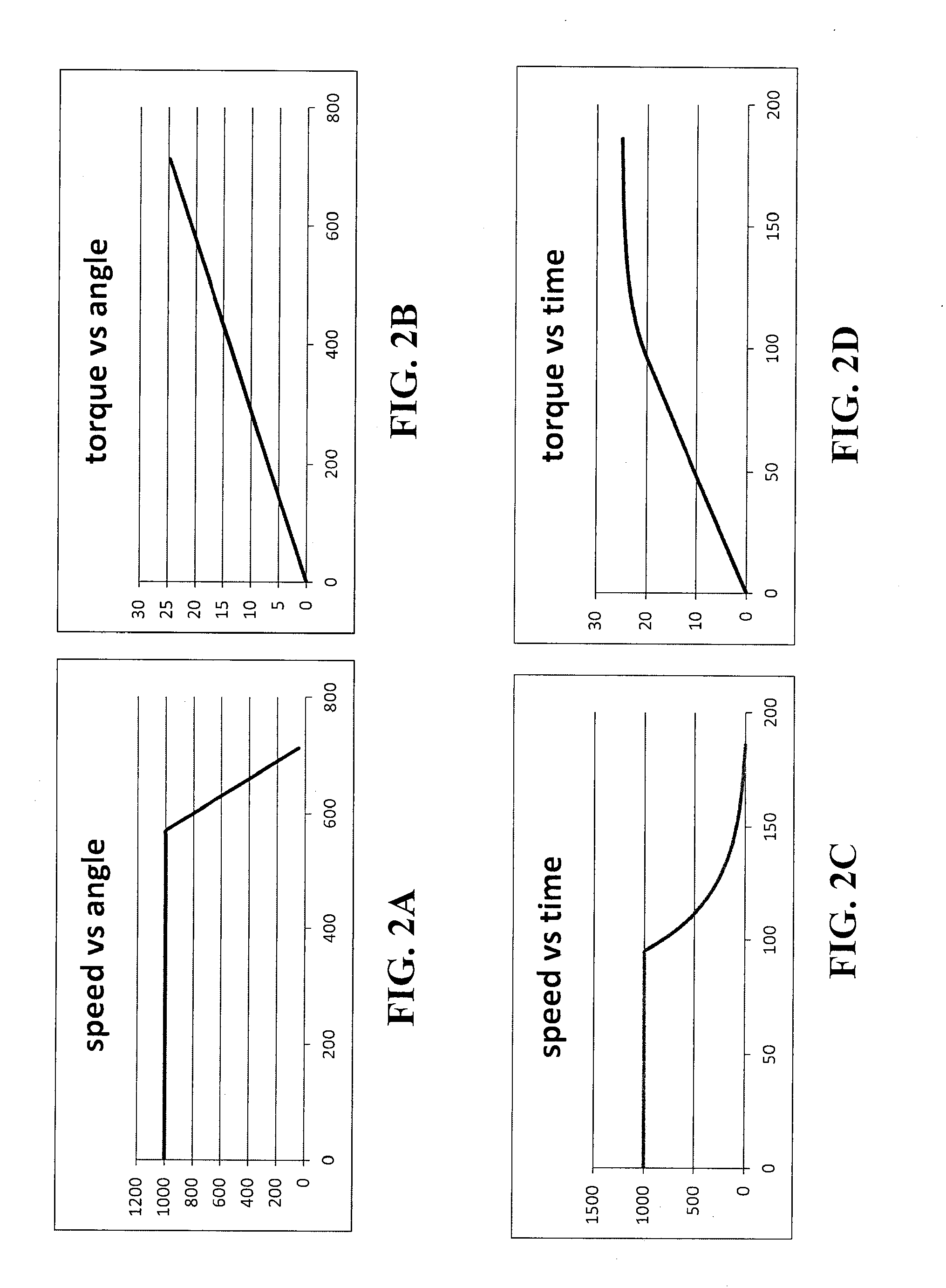
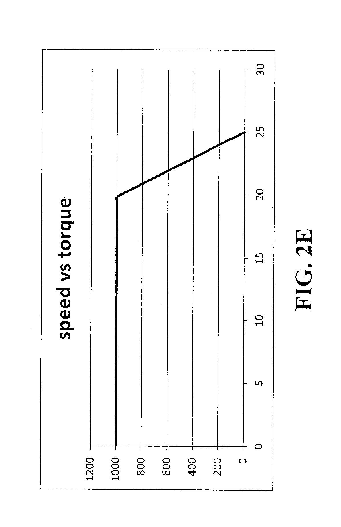
[0008]One or more embodiments of the present invention provide a torque-controlling algorithm for a controller for a torque applying tool. The controller's algorithm accounts for the kinetic energy of the rotating spindle of the tool and / or a responsiveness of the tool to desired changes in rotational speed so as to provide a fast fastening cycle time while avoiding overshoot. Moreover, a shorter cycle time may result in reduced adverse heating of the tool during repeated fastening cycles.

[0009]According to one or more embodiments, the algorithm accounts for tool parameters such as the tool's time constant of speed control.

[0010]According to one or more embodiments, the algorithm provides fast cycle times for both soft and hard joints without retuning the controller when changing between different joints (e.g., from a fastening cycle for a soft joint to a fasten...


PUM

PropertyMeasurementUnit
Frequencyaaaaaaaaaa
Timeaaaaaaaaaa
Angleaaaaaaaaaa

Abstract

A torque applying system includes a torque applying tool having a motor and rotating output spindle, a torque sensor that measures an instantaneous torque exerted by the output spindle during a fastening cycle, and a controller operatively connected to the tool to control the tool's rotational speed during the fastening cycle. The controller is programmed to control the tool's rotational speed to be [(τF−τC)/t]/r, wherein t is a time constant of speed control, τF is a target final torque for the fastening cycle, and r is a torque rate.

Description

BACKGROUND OF THE INVENTION[0001]1. Field of the Invention[0002]This invention relates to powered torque-applying tools, and more specifically, to control methods for such power tools.[0003]2. Description of Related Art[0004]Computer-controlled, torque-applying power tools (e.g., fluid or electric powered tools) are typically used in production environments to secure threaded fasteners (e.g., nuts and bolts) into joints. Such power tools are typically coupled to a controller. The tool usually has a high-speed, high-torque motor coupled to a universal adapter head. Various interchangeable bits (e.g., bits appropriate for hex-head bolts and hexagonal nuts) are connected to the head in order to drive threaded fasteners.[0005]The controller controls the power supply (e.g. fluid or electricity) for each handheld unit, and also monitors such parameters as the instantaneous tool speed and instantaneous applied torque. In a typical fastening job, fasteners are tightened to a predetermined, ...

Claims


Application Information

Patent Timeline
IPC IPC(8): B23Q15/007B23P11/00
CPCB25B23/14Y10T29/49766Y10T29/49767G05D17/02
Inventor KHALAF, ZUHER NAIMNAUMANN, WILLIAM LLOYD
Owner STANLEY WORKS THE
Why Eureka
Try Eureka