Side loader arm for refuse collection vehicle

a technology for side loading and refuse, which is applied in the direction of refuse vehicles, transportation and packaging, etc., can solve the problems of inability to get as close to the container of refuse, inability to access narrow alleys, and inherent risks, so as to reduce the impact force, reduce the wear and misalignment of parts, and accelerate the cycle time

Active Publication Date: 2016-08-02
AMREP MFG CO LLC
View PDF16 Cites 13 Cited by
  • Summary
  • Abstract
  • Description
  • Claims
  • Application Information

AI Technical Summary

Benefits of technology

[0008]The lower arm is pivotally mounted at opposing ends, with the lower end of the lower arm pivotally mounted to a laterally extending rail that moves the lower end toward and away from the vehicle during use. The upper end of the lower arm is pivotally mounted to a support post mounted to the vehicle and constrained to move in a generally vertical direction so that as the lower end of the lower arm moves away from or toward the vehicle the upper end will rise or fall as needed to allow lateral, generally horizontal movement of the lower end. Telescoping posts are believed suitable for the vertical motion. The lower arm portion, the laterally extending rail and the vertical support posts on the vehicle form three sides of a triangle, with the generally vertical support posts allowing the vertical length of the triangle to change as the length of the laterally extending rail changes and as the included angles of the triangle change. Pivotally mounting the lower arm at the top and bottom and allowing vertical movement of the top pivot mount allows the lower end of the lower arm portion to remain generally horizontal as the arm moves extends from the vehicle, making it easier to position the grippers to grab and lift refuse containers, and making it easier to set the containers down on the ground at a desired location, after they are emptied.
[0010]Extendable hydraulic pistons are believed suitable for the dumping rotation and retraction of the pistons may return the carriage, gripper and (empty) refuse container to the original position with aligned upper tracks so the carriage and connected parts may roll toward the ground to deposit the refuse container and pick up another one. This construction and operation allows a controlled emptying of the refuse containers. Because the carriage and connected parts need not be driven against the end of the upper arm by gravity as occurs when the end of the track curves downward as in prior art candy-cane shaped-arms, the impact forces, wear and misalignment of parts is reduced. The need to control the speed of the carriage toward the end of the arm as in the prior art where the candy cane curved downward, is also reduced or eliminated. Moreover, the rotation of the upper arm portion carriage, grippers and refuse container in order to dump the full refuse container, and then rotate the upper arm portion to align it with the lower arm portion to reposition the empty container for return to the ground is believed to be faster than the prior art, allowing a faster cycle time.
[0011]The upper carriage and associated parts may be driven by various mechanisms, including endless chain drives with a sprocket and optional gearing of the motor and drive chain assembly. Preferably though, a hydraulic drive is used in which two hydraulic carriage pistons are mounted to a lower carriage so the carriage pistons extend in opposing directions along the length of the lower arm portion. The lower carriage moves on a lower track beneath the upper track and preferably separated therefrom by a divider, with the lower track extending most of the length of the lower arm portion. One carriage drive piston fastens to the vehicle or the upper end of the arm to move the lower carriage toward and away from that upper end of the arm. The other carriage drive piston moves a lower return roller mounted to a wheeled shaft in order to move that wheeled roller along the lower track toward and away from the bottom end of the lower arm. A flexible, elongated member such as a wire rope, belt or preferably a chain has a first end fastened to the vehicle or the upper end of the lower arm so it doesn't move and has the other end fastened to the upper carriage, preferably at its upper end. The chain passes the lower carriage, reverses direction at the lower return roller to pass on the other side of the lower carriage before passing over an upper return roller that is straddled by the opposing tracks of the upper, curved arm portion, and then extends along the upper side of the lower arm section to connect to the upper carriage. As the carriage chain drive pistons extend the effective length of the chain is shortened and the upper carriage, gripper and refuse container move from the ground to the dump position. The chain wraps around at least one sprocket connected to the carriage pistons so that extension and contraction of the pistons move the upper carriage, gripper and refuse container. As the chain drive pistons retract the effective length of the chain lengthens and the upper carriage and associated parts roll down the arms toward the ground for unloading and picking up the next refuse container. The hydraulic pistons extending in opposing directions cause the chain length to change more rapidly than even a geared rotary motor achieves and is believed to be much faster than prior art drives using electric motors. Further, the extension of the hydraulic drive pistons and the chain length may be selected to suit the specific needs and more accurately control the position of the upper carriage on the upper and lower arms.
[0017]A flexible, elongated drive member has a first end connected to the upper carriage and a second end connected to the vehicle, directly or indirectly as being connected to the side supports or the side plates that are connected to the side supports. The elongated drive member passes over at least a first rotating part at the top end of the second arm which reverses the direction of the elongated drive member a second return rotating part on the positionable shaft to also reverse the direction of the elongated drive member so that extension and retraction of the first and second chain drive pistons a total distance X causes the second return rotating part to move a total distance X and the upper carriage to move a distance greater than X.

Problems solved by technology

Loading from the front of the vehicle as in U.S. Pat. No. 6,071,058 requires sufficient access so the front of the large refuse vehicle can approach the refuse container and such access is not possible in narrow alleys.
Also, front loading lifts the refuse container over the vehicle cab and operator posing inherent risks if the container or its contents fall onto the cab during operation.
Unfortunately, a side loading refuse vehicle cannot always get as close to the refuse container for ease of pick-up compared to a front loading vehicles.
Thus, side loading refuse vehicles usually have mechanisms to extend from the vehicle and engage the refuse container and that increases complexity.
But the articulation joints are subject to wear and impart lateral movement to the assembly holding the refuse container when the arm is in the extended position.
The movement of the arm and carriage rely on a series of pulleys, gears and motors which too often wear, break, or for various other reasons become misaligned sufficiently to require repair.
Further, the movement of the carriage, grippers and refuse container and parts around the curved end of the arm caused the container to undergo a rapid acceleration and rotation which comes to an abrupt stop when the carriage hits a stop and that jars the single-piece arm mechanism, contributing to wear, misalignment and breakage.

Method used


Image

  • Side loader arm for refuse collection vehicle
  • Side loader arm for refuse collection vehicle
  • Side loader arm for refuse collection vehicle

Examples


Embodiment Construction

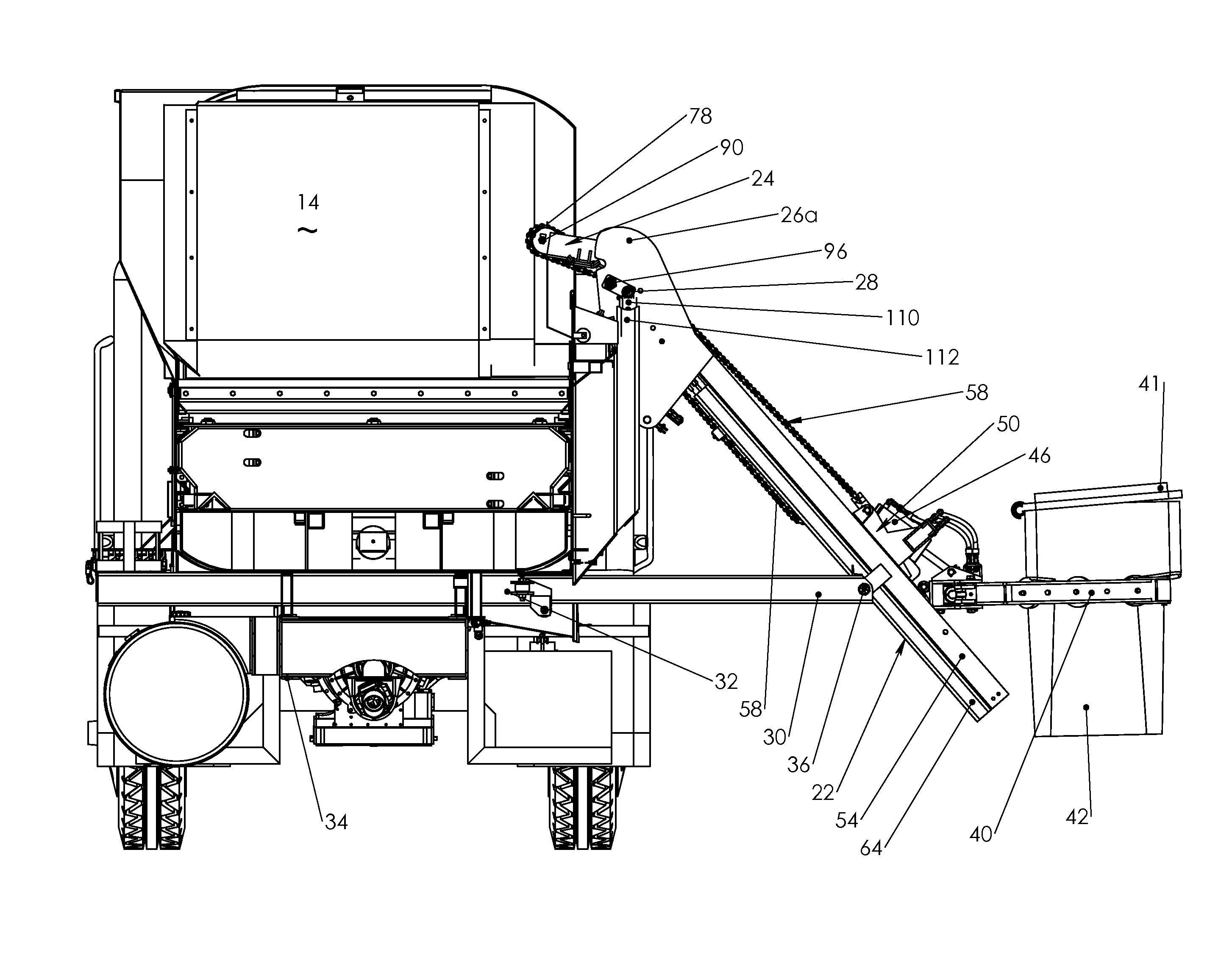
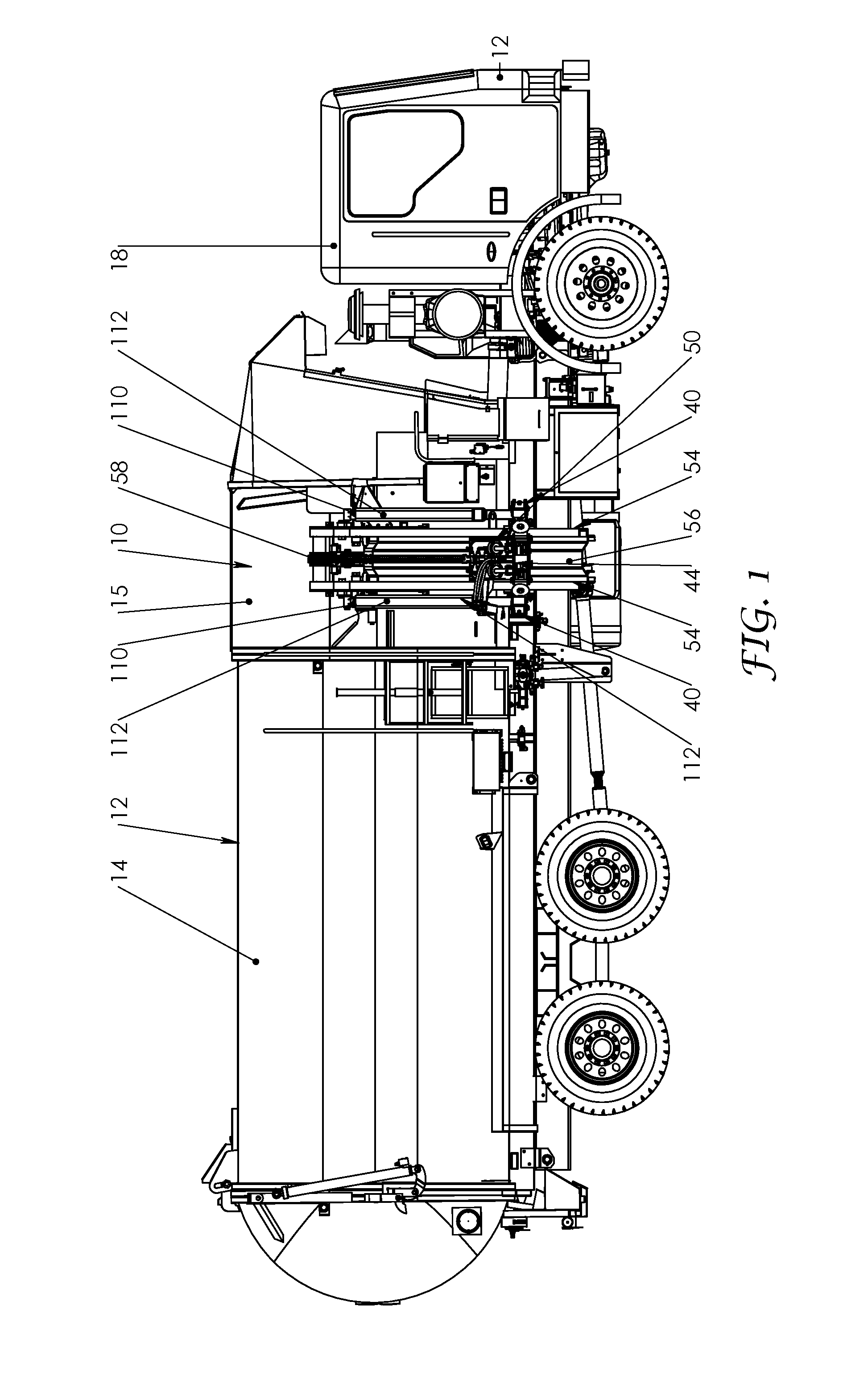
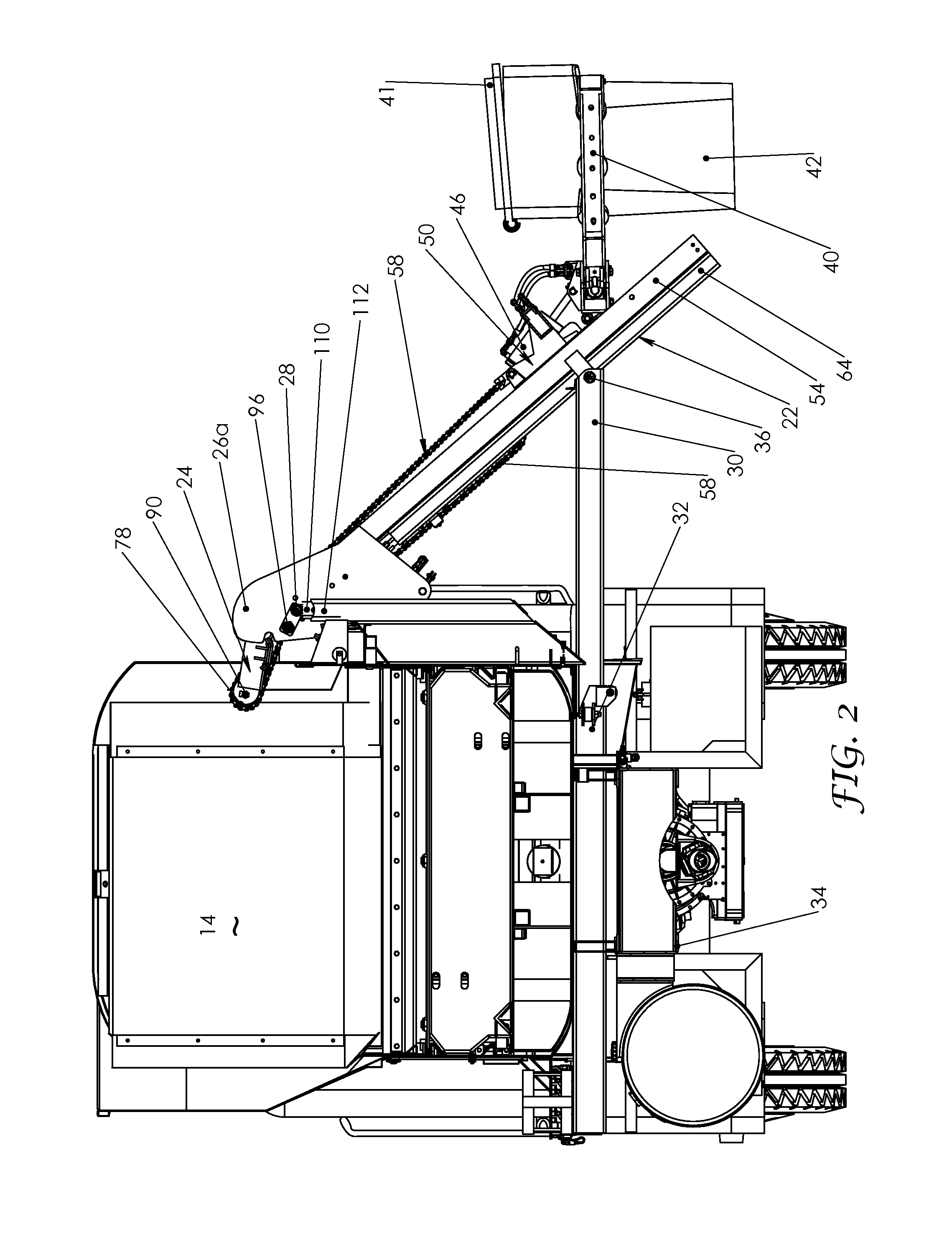
[0039]Referring to FIGS. 1-2, a side loader 10 is mounted to the side of refuse collection vehicle 12 which has a long hollow body 14 into which refuse is compacted as is known in the art. The front end of the body 14 has an upwardly opening hopper section 15 into which a refuse container is dumped. A cab 18 is at the front of the vehicle for steerage of the vehicle and operative control of the side loader 10, although additional or redundant controls may be placed on the side of the vehicle 12 adjacent the side loader. As used herein the relative terms above, below, upper, lower, top, bottom refer to the relative directions or positions along a vertical axis perpendicular to the ground surface on which the vehicle 10 rests. The lateral direction refers to a direction more parallel to the ground and relative to the vehicle 10. The relative directions front, back, forward and backward refer to the relative position or direction along longitudinal axis 21 of the vehicle 12 with front ...


PUM


Abstract

A side loader for a refuse vehicle has a laterally extendable first arm with an upper carriage connected to a gripper to releasably engage refuse containers. A second curved arm has a first position abutting the top end of the first arm so the upper carriage can reciprocate along the first and second arms. The second arm has a second, rotated position which dumps the refuse container into the vehicle. A drive chain connected to the upper carriage passes over a return roller which changes the direction of the chain before it is connected to the vehicle. A lower carriage reciprocates along the lower side of the first arm and holds two oppositely directed, hydraulic pistons. One piston moves the lower carriage relative to the vehicle and the other moves the return roller to alter the effective chain length and move the upper carriage faster than the lower carriage.

Description

CROSS-REFERENCE TO RELATED APPLICATIONS[0001]The application claims the benefit under 35 U.S.C. §119(e) to Provisional Patent Application No. 61 / 909,814 filed Nov. 27, 2013, and Provisional Patent Application No. 61 / 921,295 filed Dec. 27, 2013 the entire contents of which are incorporated herein by reference.STATEMENT RE: FEDERALLY SPONSORED RESEARCH / DEVELOPMENT[0002]Not ApplicableBACKGROUND[0003]Refuse collection vehicles can pick up and empty refuse containers from the front of the vehicle or from the side. Loading from the front of the vehicle as in U.S. Pat. No. 6,071,058 requires sufficient access so the front of the large refuse vehicle can approach the refuse container and such access is not possible in narrow alleys. Also, front loading lifts the refuse container over the vehicle cab and operator posing inherent risks if the container or its contents fall onto the cab during operation. In contrast, side-loading refuse vehicles need only drive alongside a refuse container and...

Claims


Application Information

Patent Timeline
Patent Type & Authority Patents(United States)
IPC IPC(8): B65F3/02
CPCB65F3/02B65F2003/025B65F2003/023B65F3/08B65F2003/0276
Inventor GHIBAUDO, GABRIEL A.
Owner AMREP MFG CO LLC
Why Eureka
Try Eureka