Deinterlacer using block-based motion detection

a block-based motion detection and motion detection technology, applied in the field of deinterlacing video information, can solve the problems of pixel-based motion detection failing in burst noise situations, correlation is generally not exploited in pixel-based motion detection, burst noise, etc., and achieves low computational intensity, low cost, and high volume.

Active Publication Date: 2007-05-15
WALLACE DARIEN K
View PDF14 Cites 16 Cited by
  • Summary
  • Abstract
  • Description
  • Claims
  • Application Information

AI Technical Summary

Benefits of technology

[0010]If the motion characteristic is not detected for a given block of pixels, then interline gaps in the block are filled using temporal interpolation. If, on the other hand, the motion characteristic is detected then the interline gaps are filled using spatial interpolation. To maintain interpolation accuracy without unduly increasing complexity of the integrated circuit, a less computationally intensive high angle spatial interpolation method is employed where a low angle tilt condition is not detected. A more accurate but more computationally intensive low angle spatial interpolation method can therefore be advantageously employed to interpolation in low angle tilt conditions.
[0011]The integrated circuit is designed and is specially adapted for high volume and low production cost applications including, for example, the high volume consumer television market. Integrated circuit cost is reduced by reducing the cost of memories used to pass pixel data from a field memory to interpolation circuitry. In one embodiment, the memories include three segment buffers. A memory control block on the integrated circuit retrieves new pixels to be processed from the field memory and writes them into a part of a segment buffer at the same time that the interpolation circuitry is reading other pixels from other parts of the segment buffer. A certain amount of pipelining is therefore employed in the writing and reading of the segment buffer. This pipelining increases the overall proportion of the time that the memory control block is writing pixel data into the segment buffers. Because the segment buffers are receiving pixel data from the memory control block during a larger proportion of the time, the type of memory employed to realize the segment buffer can have relaxed memory access bandwidth requirements. This allows the overall cost of the integrated circuit to be reduced. Rather than reading entire 720 pixel scan lines out of the field memory to support the block-based motion detection and interpolation processes, smaller segments of scan lines are read out of the field memory. This reduces memory access bandwidth requirements on the field memory and therefore further reduces system cost. Moreover, reading segments of lines out of the field memory rather than entire scan lines reduces the amount of memory required to pass information from the field memory to the interpolation circuitry. This reduces system cost still further.

Problems solved by technology

This correlation is, however, generally not exploited in pixel-based motion detection.
Secondly, pixel-based motion detection generally uses information from only a few intensity values around the pixel for which motion is being estimated.
Most noises are, however, burst noises and pixel-based motion detection fails in burst noise situations.
Pixel-based motion detection may fail in such situations because pixel values do not change between successive video fields.
Unfortunately, some real video includes pixel patterns where there is more than one pixel pair with the smallest difference.
Moreover, the pair with the smallest difference may not generate the best interpolation result.
Such motion compensation techniques often do not do a job of predicting motion for use in deinterlacers.
Using simple spatial displacement to detect this type of motion often results in poor decisions.
Additionally, using a displacement vector to interpolate often does not obtain adequately accurate results for deinterlacing applications.
Finding an accurate match in such a scenario is often difficult without a more noise-tolerant motion detection scheme.
In addition to these problems, motion compensation is computationally complex.
The cost of realizing a deinterlacer using this technique may be undesirably high.
The required memory bandwidth of the pixel storing memory is also generally high, which further increases system cost because higher performance memories need to be employed.

Method used


Image

  • Deinterlacer using block-based motion detection
  • Deinterlacer using block-based motion detection
  • Deinterlacer using block-based motion detection

Examples


Embodiment Construction

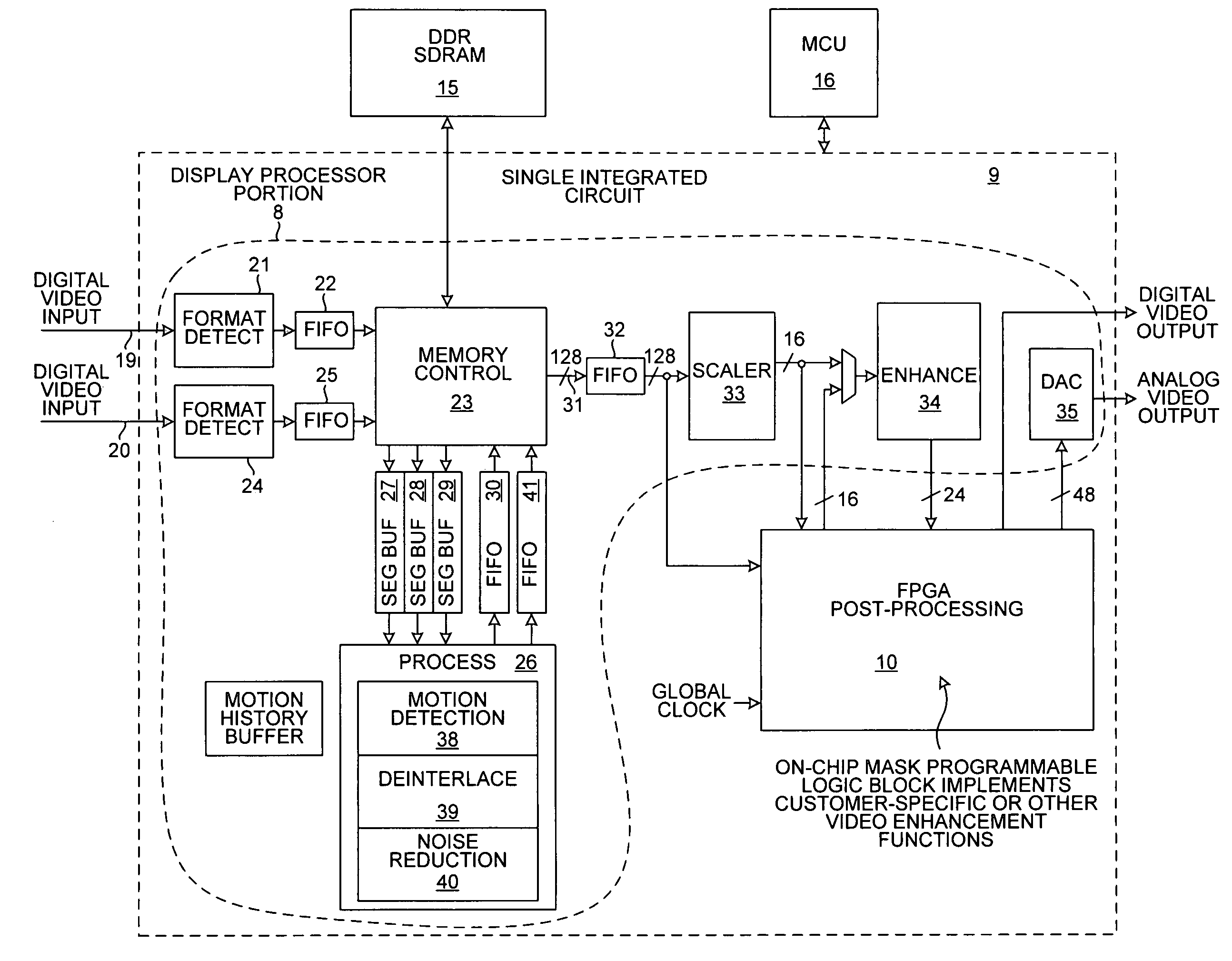
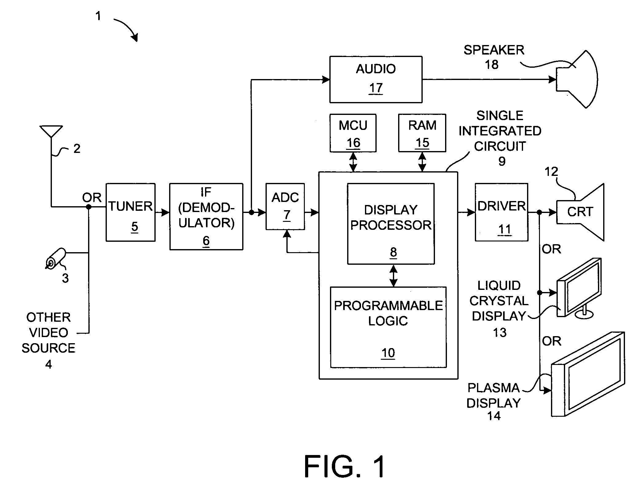
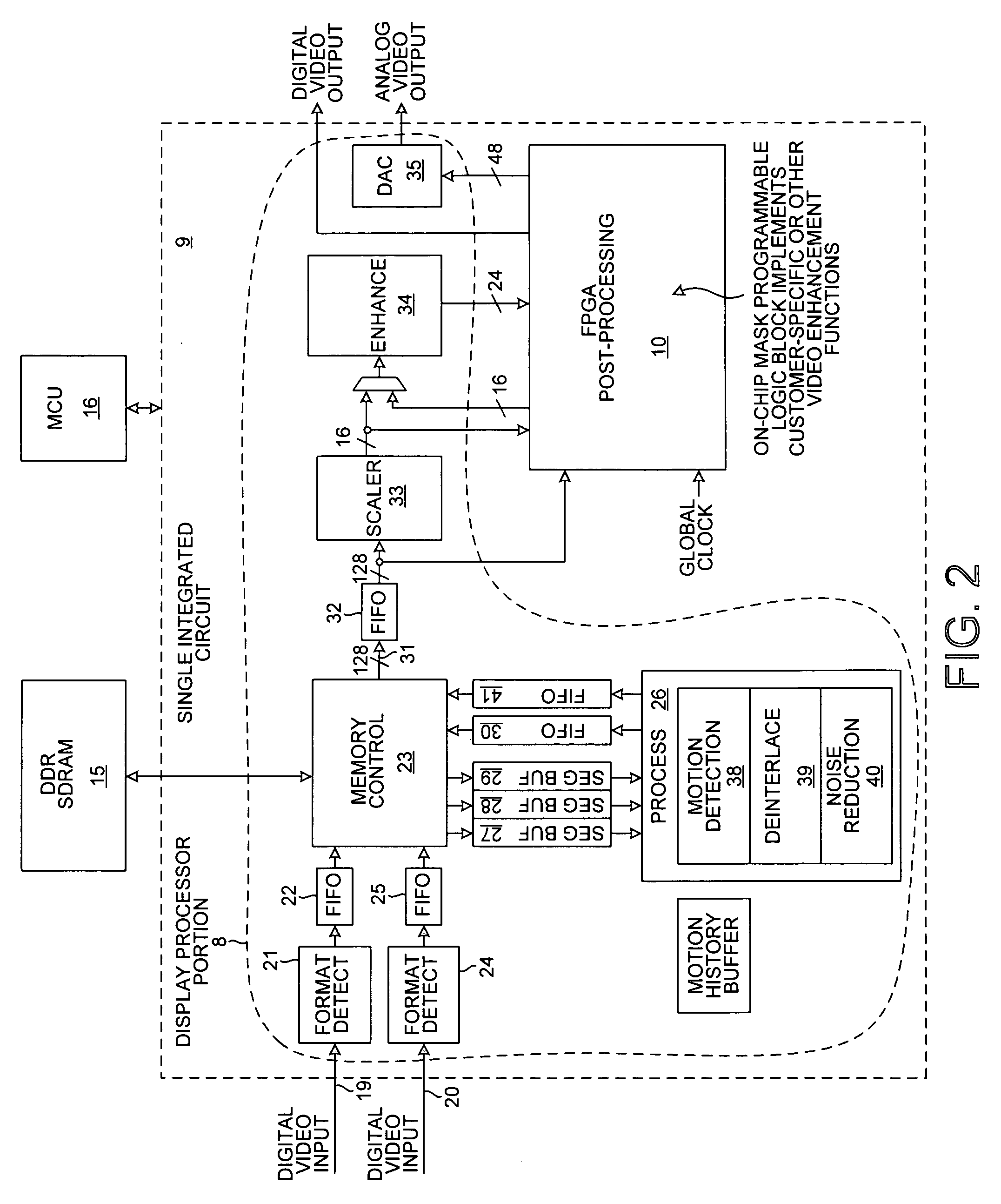
[0024]FIG. 1 is a simplified system level diagram of the electronics of a video display device 1 in accordance with one embodiment of the present invention. An incoming signal is received onto the video display device, for example, from an antenna 2, a coaxial cable 3, or another video source 4. The signal passes through a tuner 5, an IF demodulator 6, an analog-to-digital converter 7, and to a display processor 8 within an integrated circuit 9. The display processor 8 performs deinterlacing and scaling. A programmable logic portion 10 of integrated circuit 9, either independently or in concert with parts of the display processor 8, performs one or more enhancement functions. The resulting deinterlaced video signal is output from integrated circuit 9 to driver 11 and to a display device. The display device may, for example, be a cathode ray tube (CRT) 12, a liquid crystal display (LCD) screen 13, a plasma display 14 or other display device usable to view video. Frames of video infor...


PUM


Abstract

A display processor integrated circuit includes a display processor portion and an on-chip programmable logic portion. The programmable logic portion can be configured to implement custom video and/or image enhancement functions. The display processor portion performs block-based motion detection. If no motion is detected for a given block of pixels, then interline gaps in the block are filled using temporal interpolation. If motion is detected, then interline gaps are filled using spatial interpolation. To maintain accuracy without unduly increasing computational complexity, a less complex high angle spatial interpolation method is employed where a low angle tilt condition is not detected. A more computationally intensive low angle spatial interpolation method can therefore be employed in low angle tilt conditions. Integrated circuit cost is reduced by employing pipelining to write parts of segment buffers at the same time that other parts are being read to perform the interpolation process.

Description

CROSS REFERENCE TO RELATED APPLICATION[0001]This application claims the benefit under 35 U.S.C. §120 of, and is a continuation-in-part of, of U.S. patent application Ser. No. 10 / 235,628, by Chan et al., entitled “Display Processor Integrated Circuit With On-Chip Programmable Logic For Implementing Custom Enhancement Functions,” filed Sep. 4, 2002 (the subject matter of the above-identified patent application is incorporated herein by reference).TECHNICAL FIELD[0002]This application relates to deinterlacing of video information.BACKGROUND INFORMATION[0003]Video information in some video formats is interlaced. In one format, an image is displayed by painting every other line of pixels on a display, and then coming back and painting the intervening lines of pixels. For example, the odd scan lines are painted on the screen one by one, and then the even scan lines are painted. The entire image is called a frame. The first set of lines is a first field, and the second set of lines is a se...

Claims


Application Information

Patent Timeline
Patent Type & Authority Patents(United States)
IPC IPC(8): H04N7/01G06T5/00G09G5/36H04N5/21
CPCG09G5/363G06T3/4023G09G2310/0229G09G2340/0407H04N5/21G09G2320/106H04N7/012
Inventor ZHOU, QINGGANGNAGAKURA, CLYDE H.WU, SHENG-FUCHAN, ANDREW K.
Owner WALLACE DARIEN K
Why Eureka
Try Eureka