High capacity passive optical network

a passive optical network, high-capacity technology, applied in the direction of multiplex communication, electrical equipment, electromagnetic network arrangements, etc., can solve the problems of incompatibility between the physical size of the network and the minimum length of the transmitted packet, and the inefficiency of the network for short packets, so as to reduce the size and cost of the subscriber station equipment

Inactive Publication Date: 2007-05-15
RPX CLEARINGHOUSE
View PDF9 Cites 39 Cited by
  • Summary
  • Abstract
  • Description
  • Claims
  • Application Information

AI Technical Summary

Benefits of technology

[0020]Advantageously, detection of collisions is performed by the subscriber stations rather than within the network connecting them, thereby avoiding the need for active collision detection within the connecting optical network.
[0053]Advantageously, this reduces size and cost of the subscriber station equipment.

Problems solved by technology

Other nodes on the network might also start transmitting when they detect that the medium is free, but might not know of other nearly simultaneous transmissions by another node because of the inherent transmission delay of the medium.
Simultaneous transmission results in a ‘collision’ which must be detected by all nodes simultaneously attempting to transmit.
A disadvantage with this system is that it requires active electronics in the repeater which is not compatible with operator requirements to remove active electronics from street locations.
For high speed networks such as these using a passive optical star coupler, this results in a tradeoff between the physical size of the network and the minimum length of the transmitted packet.
A problem with this is that such a network is very inefficient for short packets, which must be extended to the minimum packet size to guarantee detection of any possible collisions.
A further problem is that, the maximum permitted packet size on an Ethernet network is around 1500 bytes; any network including Ethernet segments cannot therefore use a larger packet size than this unless data is reformatted.
It is then difficult to detect collisions, since a weak signal can be swamped by a strong one.
Indeed, when practical tolerance levels are fully taken into account, it may not be possible to build a suitable receiver economically.
In practice, this system is rarely used because of the difficulty of implementing a receiver capable of reliable collision detection.
The problems associated with implementing such a receiver can be expected to be much more severe at a bit rate of 1 Gbit / s.

Method used


Image

  • High capacity passive optical network
  • High capacity passive optical network
  • High capacity passive optical network

Examples


Embodiment Construction

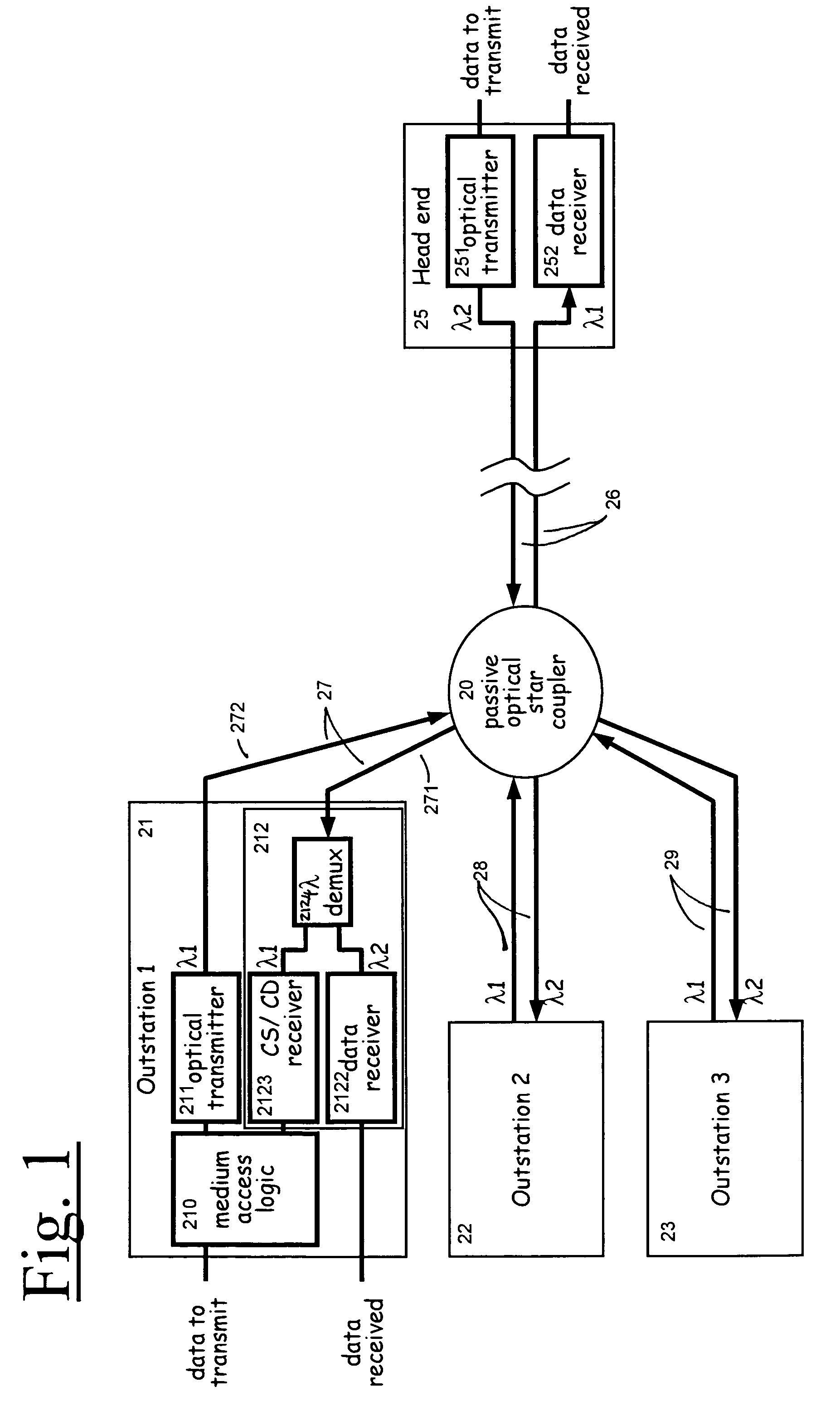
[0074]Referring now to FIG. 1, there is shown a CS / CD network suitable for use as an access network, and comprising a single head end 25 connecting to a number of subscriber outstations 21–23 via a passive optical star coupler 20. Typically, the distance between any two outstations is assumed to be relatively small, perhaps 200 m, but the distance from the head end to the coupler may be much greater, for example up to around 5 km. The coupler may be located at a convenient point close to the subscribers' outstations (for example in a street cabinet) and, being a passive arrangment, requires no electrical power supply.

[0075]Each outstation comprises an optical transmitter 211 transmitting on frequency λ1 and controlled by a medium access logic unit 210, and an optical receiver arrangement 212 arranged to receive signals on both frequency's λ1 and λ2.

[0076]The optical receiver arrangement may receive signals on both λ1 and λ2, and splits them by means of demux 2124, providing the data...


PUM


Abstract

A passive optical network suitable for use as a telecommunications access network, having a head-end transmitting in a first optical frequency and one or more subscriber stations transmitting on a second common optical frequency. A carrier sense, multiple access protocol, with collision detection, is used, the collision detection being performed in the subscriber and head-end stations.

Description

FIELD OF THE INVENTION [0001]The present invention relates to apparatus and related methods of operation for providing a high capacity passive optical network, and a system incorporating the same.BACKGROUND OF THE INVENTION[0002]This invention relates to fibre in the loop access networks, and in particular to fibre to the home (FTTH).[0003]A characteristic of known FTTH networks is that customers tend to exist in groups situated geographically close to each other (say, within 200 meters), but the head end (or central office) may be some kilometers away for example, 5 km.[0004]In networks where multiple nodes share a common medium, a multiple access protocol is needed to manage access to the medium such that individual nodes on the network can transmit their information successfully without interruption by transmission attempts from other nodes. Ethernet (IEEE standard 802.3) has adopted a ‘Carrier Sense’ with ‘Collision Detection’ protocol. When a node has data to transmit, it monit...

Claims


Application Information

Patent Timeline
Patent Type & Authority Patents(United States)
IPC IPC(8): H04B10/20
CPCH04B10/272
Inventor UNITT, BRIANGRANT, MICHAELFARRINGTON, JEFFREYPHILLIPS, DAVID
Owner RPX CLEARINGHOUSE
Why Eureka
Try Eureka