
Method and system for fault detection and exclusion for multi-sensor navigation systems

Active Publication Date: 2007-05-15
ROCKWELL COLLINS INC
View PDF4 Cites 166 Cited by
  • Summary
  • Abstract
  • Description
  • Claims
  • Application Information

AI Technical Summary

Benefits of technology

[0010]It is an advantage of the present invention to provide enhanced ability to obtain sufficient probability levels for the detection threshold and HPL.
[0011]It is another advantage of the present invention to predict HPL without the need for making real GPS measurements.
[0012]It is another object of the present invention to provide a tightly integrated GPS / inertial sensor system which can be used for the primary means of navigation from oceanic / remote down to non-precision approach phases of flight.
[0013]It is another feature of the present invention to employ a hybrid algorithm which combines two independent and parallel methods for fault detection and fault exclusion.
[0014]It is an advantage of the present invention to provide for speedier determination of fault exclusions in some circumstances.
[0015]It is another feature of the present invention to provide an indication of HUL for a combined GPS / inertial navigation system.

Problems solved by technology

However, due to the inadequate signal-in-space integrity currently provided by GPS for civil aviation, it is generally necessary to also employ real-time fault detection and exclusion (FDE) schemes, especially when the multi-sensor system is used for primary means of navigation.
Since the current assumptions about the GPS constellation and its measurement accuracy often do not provide high enough availability of FDE to meet the primary means objectives for all phases of flight, integration of GPS with inertial sensors for integrity monitoring has received considerable attention.
After a fault is detected in prior art systems, the HPL is often operationally of little value because HPL no longer bounds the true error at the specified statistical level.
While these prior art multi-sensor systems and FDE algorithms have enjoyed success in the past, they have some drawbacks in certain circumstances.
Often these systems fail to provide a sufficiently precise probability level for the detection threshold and HPL.

Method used


Image

  • Method and system for fault detection and exclusion for multi-sensor navigation systems
  • Method and system for fault detection and exclusion for multi-sensor navigation systems
  • Method and system for fault detection and exclusion for multi-sensor navigation systems

Examples


Embodiment Construction

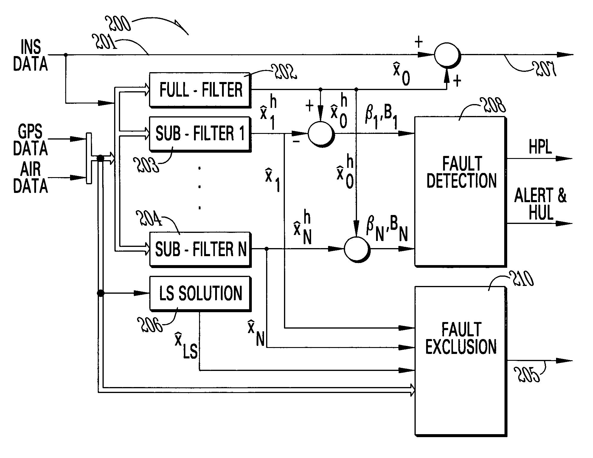
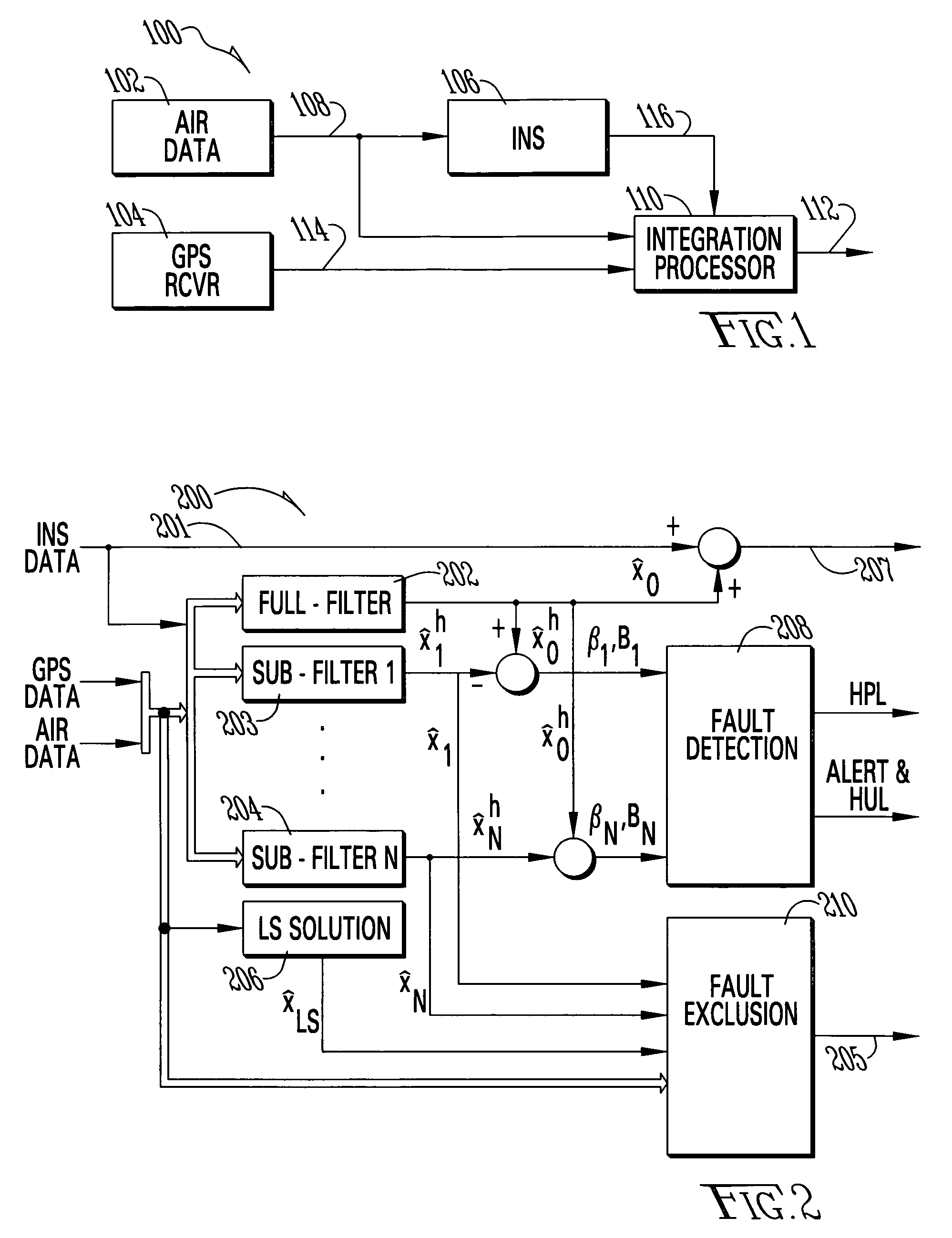
[0026]Now referring to the Figures, where like numerals refer to like matter and text throughout, and more particularly referring to FIG. 1, generally designated 100, there is shown a block diagram of the GPS / INS integration architecture of the present invention. This is an open loop integration such that there is no feedback to the INS 106 or the GPS receiver 104 from the integration processor 110. Air data 102 is shown to be provided to both the INS 106 and the integration processor 110 which outputs a corrected position 112, as well as other data including HPL, HUL, shown in FIG. 2. The proposed Kalman filter is executed in the integration processor 110. Also in FIG. 1, 108 represents an altitude line; 114 represents a pseudoranges and SV ECEF positions line; and 116 represents a position, velocity and attitude line.

[0027]Now referring to FIG. 2, there is shown the architecture, generally designated 200, of the integration processor 110. There are multiple navigation solutions fo...


PUM


Abstract

A new Fault Detection and Exclusion (FDE) approach for tightly integrated GPS / inertial sensors that combines a normalized solution separation for fault detection and a residual monitoring scheme for fault exclusion is described. The computation of the detection threshold, the horizontal protection level and the horizontal uncertainty level are also presented. This new FDE algorithm is designed to enable the tightly integrated GPS / inertial sensor to be used as a primary means of navigation sensor for civil aviation.

Description

FIELD OF THE INVENTION[0001]The present invention generally relates to aviation electronics, and more particularly relates to multi-sensor navigation systems, and even more particularly relates to methods and systems for fault detection and fault exclusion in multi-sensor navigation systems.BACKGROUND OF THE INVENTION[0002]In the past, multi-sensor navigation systems have been used with much success. These multi-sensors typically use global positioning system (GPS) receivers in combination with other inertial sensors to generate position information. However, due to the inadequate signal-in-space integrity currently provided by GPS for civil aviation, it is generally necessary to also employ real-time fault detection and exclusion (FDE) schemes, especially when the multi-sensor system is used for primary means of navigation. Since the current assumptions about the GPS constellation and its measurement accuracy often do not provide high enough availability of FDE to meet the primary ...

Claims


Application Information

Patent Timeline
IPC IPC(8): G01C21/00G01S19/20
CPCG01C21/165G01S19/20
Inventor YOUNG, SHIH-YIH R.MCGRAW, GARY A.
Owner ROCKWELL COLLINS INC
Learn More