Footwear with sealed sole construction and method for producing same

Inactive Publication Date: 2007-05-22
HAIMERL FRANZ
View PDF15 Cites 23 Cited by
  • Summary
  • Abstract
  • Description
  • Claims
  • Application Information

AI Technical Summary

Benefits of technology

[0039]In an embodiment of the invention, reactive hot-melt adhesive is used, which may be the already mentioned PU reactive hot-melt adhesive with admixed carbon particles, metal particles with electrical conductivity or particles of other materials which have an electrical conductivity of such a type that they can be selectively heated by means of microwave energy, or which have an absorbency for other types of radiation, for example infrared radiation, of such a type that they can be selectively heated by means of such radiation. As a result of the energy absorption, the particles admixed with the reactive hot-melt adhesive heat up and cause the reactive hot-melt adhesive to be heated “from the inside out”. In this process, the particles act like “heating elements” incorporated into the reactive hot-melt adhesive. Suitable selection of the heating energy allows the effect to be achieved that materials of the shoe construction other than the reactive hot-melt adhesive do not heat up, or only relatively little. The particles are, for example, in a fibrous form. The carbon particles are admixed with the reactive hot-melt adhesive with a proportion by weight in the range from about 0.1%0 to about 5%0, preferably in the range from about 0.1%0 to about 3%0 and particularly preferably with a proportion by weight of 2%0. For metal particles, ap

Problems solved by technology

However, the use of bootees is quite costly in production if the bootees are to correspond to some extent to the shape of the respective shoe.
This cannot, however, prevent water from reaching the end of the upper on the sole side, and consequently the end of the functional layer on the sole side, on the outer material of the upper, which generally conducts water by capillary effects, and consequently reaching the generally very strongly water-absorbent inner lining located on the inner side of the functional layer, via water bridges, in particular in the form of textile fibers at the cut edge o

Method used


Image

  • Footwear with sealed sole construction and method for producing same
  • Footwear with sealed sole construction and method for producing same
  • Footwear with sealed sole construction and method for producing same

Examples


first embodiment

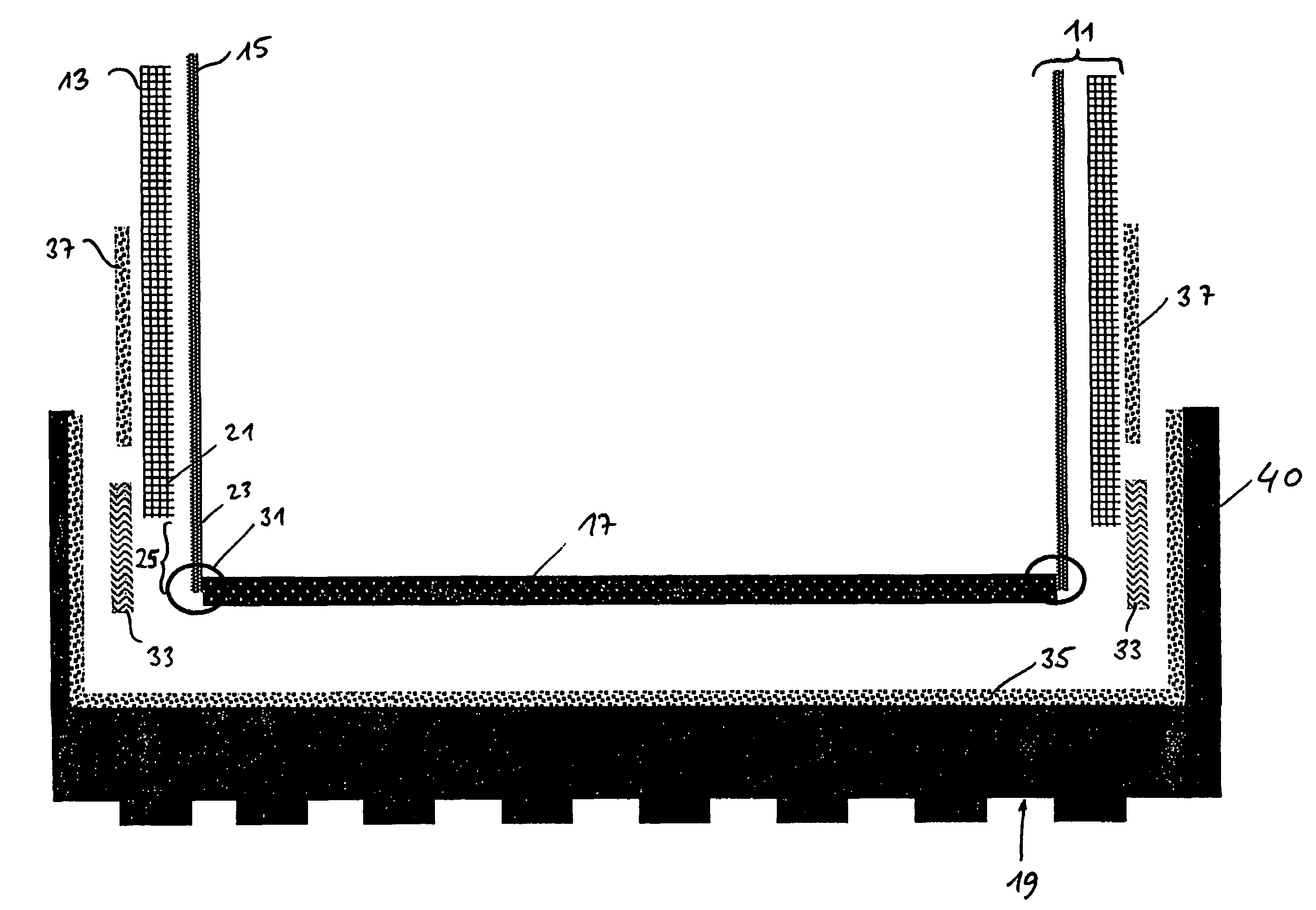
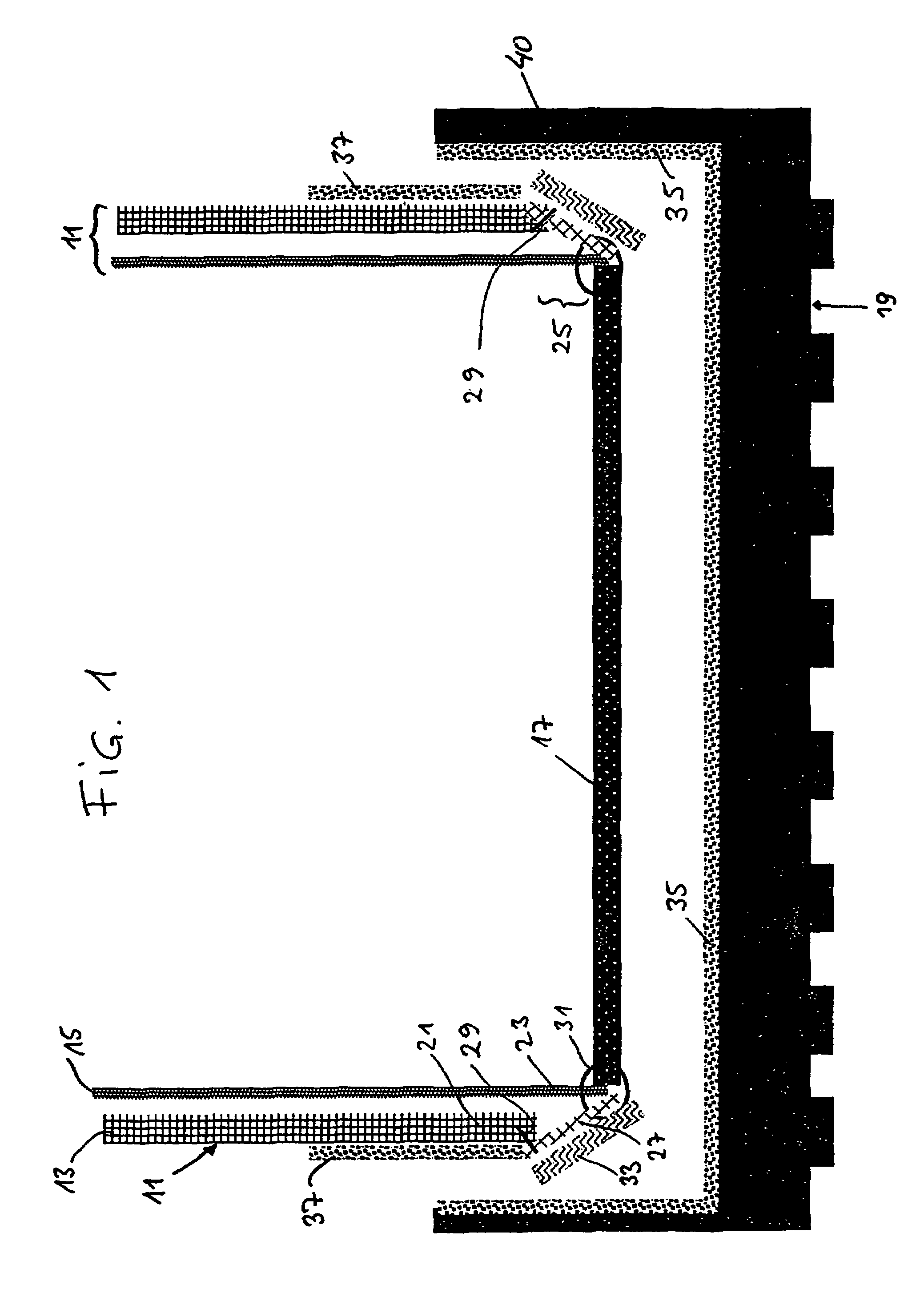
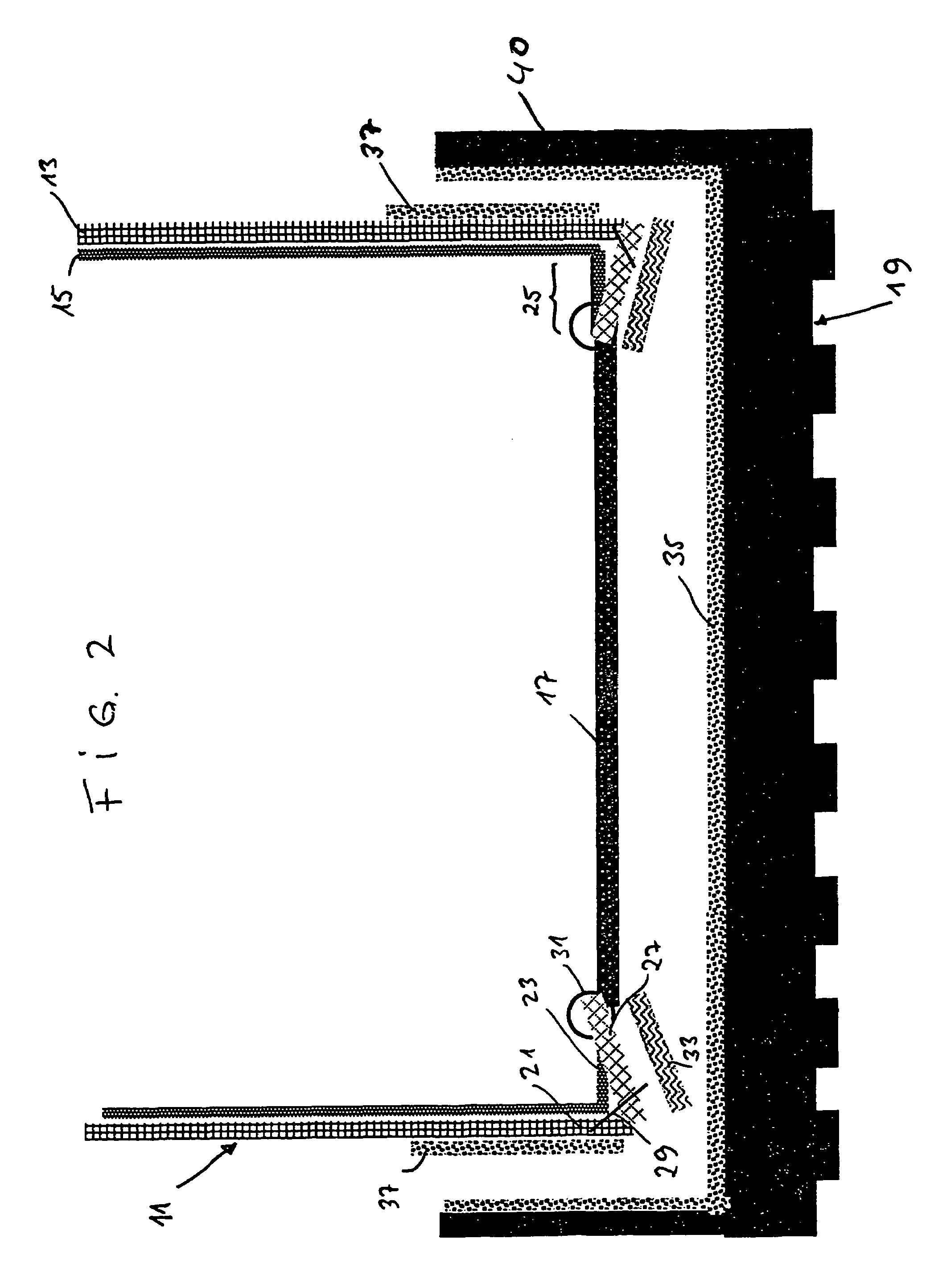
[0081]FIG. 1 shows in a highly schematized cross-sectional representation a shoe according to the invention, with an upper 11, which is constructed with an outer material 13 and a functional layer 15 lining the inner side of the latter. The functional layer 15 may be part of a functional-layer laminate, which has the functional layer and a lining layer on the inner side of the latter. Furthermore, the functional layer 15 may be provided with a textile backing (not represented) on its outer side facing the outer material 13. There are also embodiments in which the functional layer and the lining are separate layers of material.

[0082]Furthermore, FIG. 1 shows an insole 17 and a dish-like, prefabricated outsole 19, which is constructed with rubber and / or plastic. The outer material 13 and the functional layer 15 have an outer-material end region 21 or functional-layer end region 23 ending vertically, i.e. perpendicular to the tread of the outsole 19. The functional-layer end region 23 ...

third embodiment

[0089]The third embodiment, shown in FIG. 3, is shown in FIG. 4 in a partially sectioned perspective representation, but still without an outsole. This figure shows a last 41, over which the upper 11 has been pulled. As a departure from FIG. 3, in FIG. 4 a separate lining layer 43 is shown on the inner side of the functional layer 15. FIG. 4 shows the shoe construction in a state in which the reactive hot-melt adhesive has been applied only to the underside of the gauze strip 27, but has not yet been pushed through the gauze strip 27 to penetrate as far as the functional-layer end region 23.

[0090]FIG. 5 shows a shoe construction according to FIG. 4, likewise in a partially sectioned perspective representation, after the adhesive attachment of an outsole 39 to the underside of the insole 17 and to the underside of the vertical region of the upper 11. In this representation, the last 41 has already been removed from the shoe.

[0091]For better illustration, a circular detail of the sole...

fourth embodiment

[0094]In the fourth embodiment there is no connection between the lower end of the outer-material end region 21 and the lower end of the functional-layer end region 23 and the insole 17 before the adhesive attachment of the outsole 19 and before adhesive bonding with the reactive hot-melt adhesive 33 in the upper end region. Only after application of the reactive hot-melt adhesive 33 is there a connection between the outer-material end region 21 and the functional-layer end region 23 on account of the adhesive effect of the said adhesive, if the reactive hot-melt adhesive is applied to such an extent that it includes the lower edge of the outer-material end region, which is not absolutely necessary. After the adhesive attachment of the outsole 19 to the insole 17 and the upper 11, the outer-material end region 21 is also laterally fixed by means of the upturned edge 40 of the outsole 19.

[0095]The fifth embodiment, shown in FIG. 8, coincides with the fourth embodiment, shown in FIG. ...


PUM


Abstract

Footwear with an upper and a sole construction having an outsole, in which the upper is constructed with an outer material and with a waterproof functional layer at least partially lining the outer material on the inner side of the latter and having an upper end region on the sole side with an outer-material end region and a functional-layer end region, the outsole (19) is joined to the upper end region, the functional-layer end region has an overhang projecting beyond the outer-material end region and an adhesive zone which is closed in the direction of the sole periphery and comprises a reactive hot-melt adhesive which brings about waterproofness when in the fully reacted state is applied to the overhang.

Description

[0001]This application is a 371 of PCT / EP00 / 04113 filed May 8, 2000.FIELD OF THE INVENTION[0002]The invention relates to footwear with an upper, which is provided at least partially with a waterproof functional layer which is preferably water-vapor permeable, and with an outsole, in particular a cemented-on outsole. The invention also relates to a process for the production of such a shoe.TECHNICAL BACKGROUND[0003]There are shoes whose shoe upper is waterproof and water-vapor permeable because it is lined with a functional layer. A shoe upper of this type remains breathable in spite of being waterproof. Special efforts are required to ensure permanent waterproofness in the region between the end of the upper on the sole side and the sole construction.[0004]To achieve this, sock-like inserts, also known among those skilled in the art as bootees, have been used between the upper and the sole construction on the one hand and an inner lining on the other hand. Since such bootees are sha...

Claims


Application Information

Patent Timeline
IPC IPC(8): A43C13/08A43B13/38A43B7/12A43B9/12A43D21/00
CPCA43B7/125A43B9/12
Inventor HAIMERL, FRANZ
Owner HAIMERL FRANZ
Why Eureka
Try Eureka