Evaporator having heat exchanging parts juxtaposed

a technology of heat exchanger and heat exchanger, which is applied in the field of evaporators, can solve the problems of disadvantageous “blowout” temperature of coolant, and achieve the effect of reducing an area

Inactive Publication Date: 2007-05-22
CALSONIC KANSEI CORP
View PDF7 Cites 41 Cited by
  • Summary
  • Abstract
  • Description
  • Claims
  • Application Information

AI Technical Summary

Benefits of technology

[0012]In the above-mentioned situation, it is an object of the present invention to provide an evaporator including upwind-side and downwind-side opposing paths each having the flowing directions of coolant opposite to each other, the evaporator enabling a reduction of an area causing a rise in “blowout” temperature of the liquid-phase coolant due to its short supply.
[0014]Since the number of heat exchanging passages in the paths where the coolant rises is smaller than the number of heat exchanging passages in the paths where the coolant downs, it becomes possible to increase the quantity of coolant flowing in the former paths that are apt to be short in supplying the coolant. As the result, it is possible to reduce an area causing a rise in “blowout” temperature of the coolant due to the short supply.
[0018]Since the communication passage is formed integrally with the side plate, there is no need to prepare an exclusive member for the communication passage. As the result, it is possible to save the manufacturing cost of the evaporator.

Problems solved by technology

In FIG. 2B, since the wind cannot be cooled down sufficiently in areas where the liquid-phase coolant L does not flow, in other words, only gas-phase coolant G does flow, the “blowout” temperature of the coolant is elevated disadvantageously.

Method used


Image

  • Evaporator having heat exchanging parts juxtaposed
  • Evaporator having heat exchanging parts juxtaposed
  • Evaporator having heat exchanging parts juxtaposed

Examples


Embodiment Construction

[0036]Referring to the accompanying drawings, an embodiment of the present invention will be described below.

[0037]FIGS. 3 to 15B show an embodiment of the present invention. An evaporator 1 of this embodiment can be used for an evaporator that is interposed in a refrigeration cycle of an automotive air conditioner. The evaporator 1 is positioned in an air-conditioner casing inside an instrument panel of a vehicle. The evaporator 1 carries out heat exchanging between coolant flowing in the air-conditioner casing and air passing through the outside of the air-conditioner casing. In the evaporator 1, the coolant is evaporated to cool down the air.

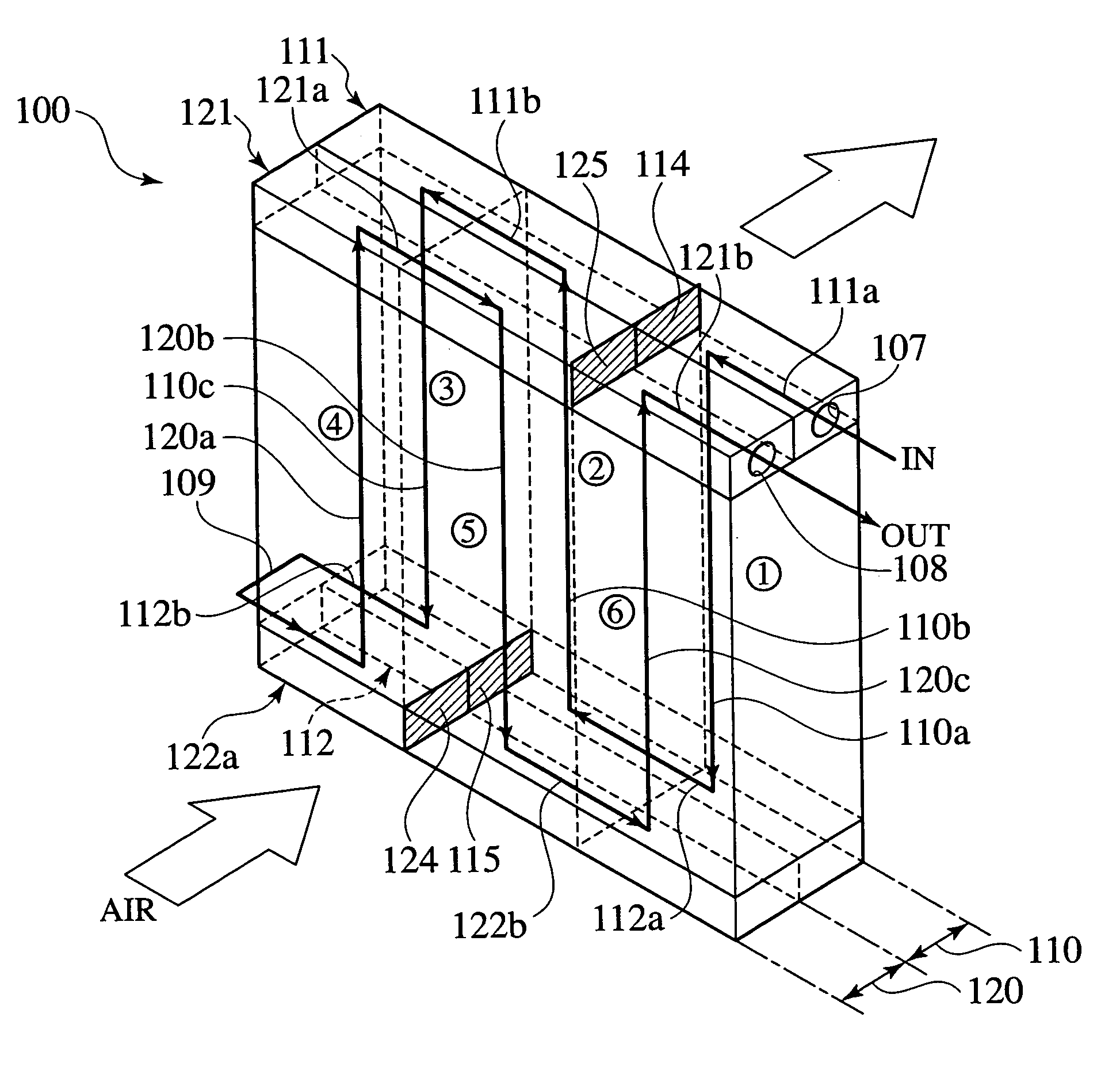
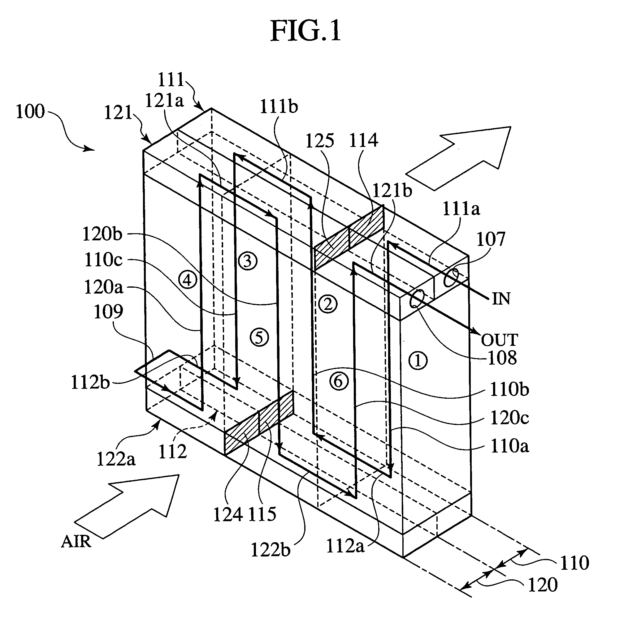
[0038]First of all, the whole structure of the evaporator 1 will be described with reference to FIG. 14, in brief.

[0039]The evaporator 1 includes two heat exchanging parts 10, 20 juxtaposed on upwind and downwind sides, respectively.

[0040]The “downwind-side” heat exchanging part 10 has an upper tank 11, a lower tank 12 and a plurality of heat...


PUM


Abstract

An evaporator includes a downwind-side heat exchanging part and an upwind-side heat exchanging part. In the heat exchanging part, paths are formed by partitions. In the evaporator, the flowing direction of coolant flowing in the upwind-side path is opposite to the flowing direction of the coolant flowing in the downwind-side path opposing to the upwind-side path. The number of heat exchanging passages in the path where the coolant rises is smaller than the number of heat exchanging passages in the paths where the coolant downs. As a result, the evaporator enables an increasing of the quantity of coolant flowing in the paths. Thus, if superimposing the upwind-side heat exchanging part on the downwind-side heat exchanging part, then it is possible to reduce an area causing a rise in blowout temperature of the coolant due to its short supply.

Description

BACKGROUND OF THE INVENTION[0001]1. Field of the Invention[0002]The present invention relates to an evaporator having two heat exchanging parts juxtaposed in the flowing direction of wind passing through the evaporator.[0003]2. Description of the Related Art[0004]An evaporator having two heat exchanging parts juxtaposed in the flowing direction of wind is disclosed in Japanese Patent Application Laid-open Nos. 6-74679, 10-238896 and 2000-105091.[0005]The inventor is developing an evaporator shown in FIG. 1. The evaporator 100 includes two heat exchanging parts juxtaposed on upwind and downwind sides in the flowing direction of wind, respectively.[0006]The “downwind-side” heat exchanging part 110 has an upper tank 111, a lower tank 112 and a plurality of heat exchanging passages between the tanks 111 and 112. These heat exchanging passages are also communicated with the tanks 111, 112. Similarly, the “upwind-side” heat exchanging part 120 has an upper tank 121, a lower tank 122 and a...

Claims


Application Information

Patent Timeline
Patent Type & Authority Patents(United States)
IPC IPC(8): F25B39/02F28D1/03F28F9/02F28F9/22F28F13/02
CPCF28D1/0333F28D2021/0085F28F2280/04
Inventor INABA, HIROYUKIKAWAMATA, TORU
Owner CALSONIC KANSEI CORP
Why Eureka
Try Eureka