Specimen holding apparatus

a technology for holding apparatuses and specimens, applied in the direction of apparatus for force/torque/work measurement, tension measurement, instruments, etc., can solve the problems of affecting the accuracy of specimen installation and removal, so as to improve the distribution of restraining forces, the process of installing and removing specimens is simple and reliable, and the effect of precise visual alignmen

Inactive Publication Date: 2007-05-22
E A FISCHIONE INSTR
View PDF15 Cites 11 Cited by
  • Summary
  • Abstract
  • Description
  • Claims
  • Application Information

AI Technical Summary

Benefits of technology

[0014]It is an object of the present invention to provide a specimen holder having the benefits of previously-known resilient restraining devices and methods, while making simpler and more reliable the process of installing and removing specimens, without compromise of the capability for observation over a wide range of tilt angles. The restraining-device system of the invention provides for precise visual alignment with the specimen, prior to application of any force on the specimen. Further, the present invention provides for loading and un-loading of specimens through operator access to the top side only of the holder; this will be recognized as an advantage to the operator by those skilled in the art of, e.g., electron microscopy. In addition, the invention provides for improved distribution of restraining forces over the surface of the specimen. This results in gentle restraint of fragile specimens, as well as the capability to restrain specimens with uneven surfaces.

Problems solved by technology

However, it has proven difficult to use by some operators because of its requirement to align three points of engagement simultaneously between the clip 27 and the body 39.
However, this approach suffers from the disadvantage that the specimen must be slid underneath the clips simultaneously to experience a restraining force from the clips.
This situation makes loading difficult, and can easily damage a fragile specimen.
This mechanism has limited ability to restrain specimens of varying thickness, and the C-shaped retaining spring has been found to be difficult to handle by some operators.
This mechanism can easily damage fragile specimens due to the rigid nature of the screw threads.
Therefore, it is difficult for an operator to pause and inspect the positioning of the specimen and the levers prior to applying the restraining force.
Also, in order to lift the jaw 103 and 104 of each lever away from the specimen, the wire legs 101 and 102 of each lever must pivot below the plane of specimen support, making it difficult for an operator to manipulate with precision.
Further, this device is difficult to make small, so as to fit easily in narrow spaces such as typically encountered in charged-particle instruments such as electron microscopes.
Known straining holders require the clamping mechanism to be removed entirely for the purpose of loading a specimen, and so are cumbersome to use.
Hence, it is desired to make each of these elements as thin as practical to achieve viewing at high tilt, as the thickness of each will limit the practical viewing angle.
However, it is also understood that the design and physical characteristics of the restraining element impose restrictions on the design and physical characteristics of the supporting structure, so that these elements are not independent of one another.

Method used


Image

  • Specimen holding apparatus
  • Specimen holding apparatus
  • Specimen holding apparatus

Examples


Embodiment Construction

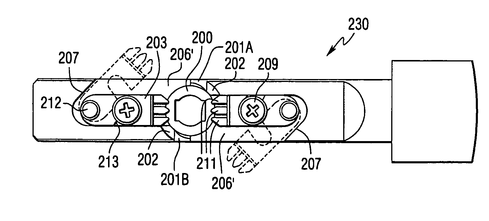
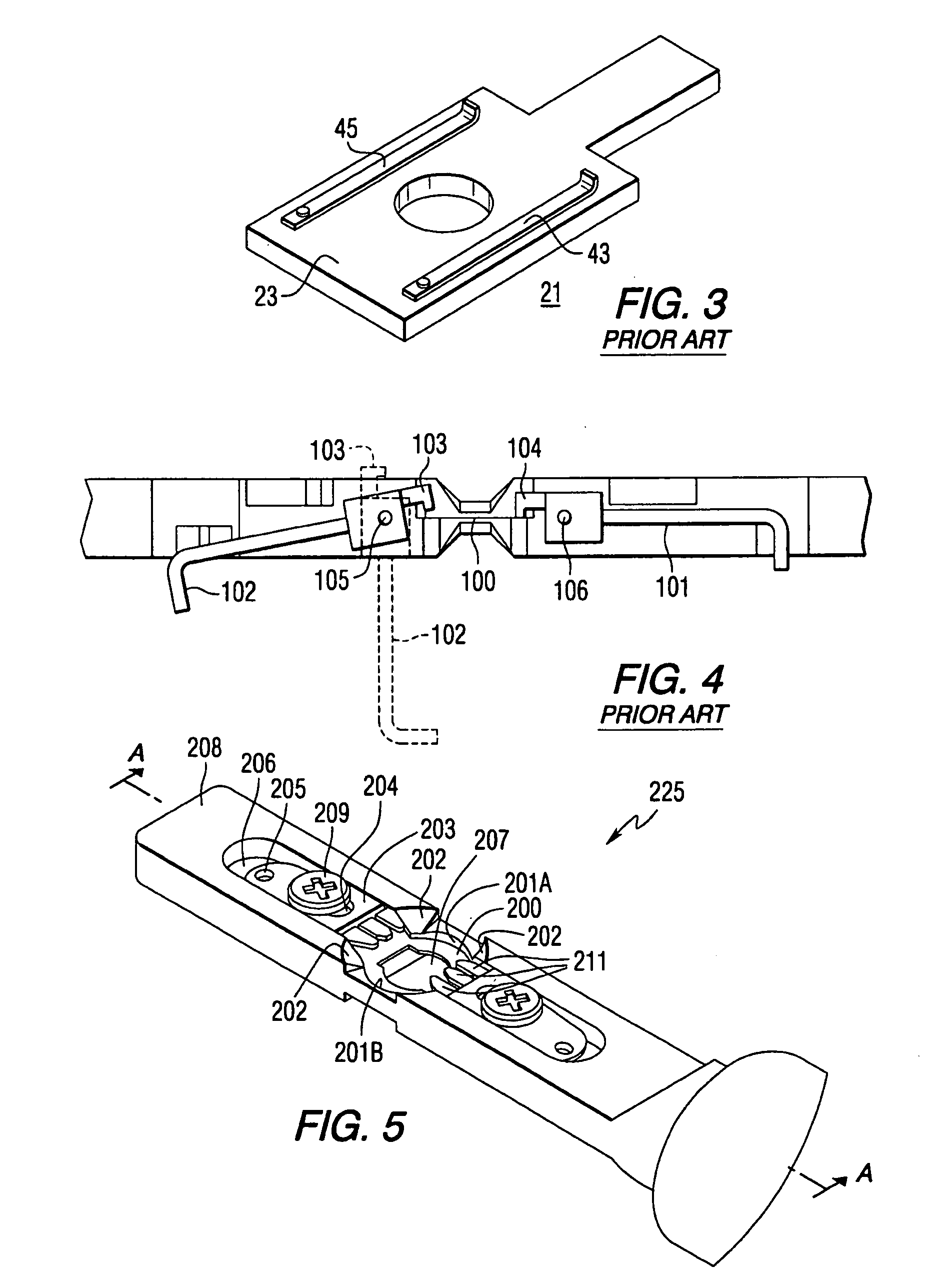
[0028]FIG. 5 is an isometric view of a specimen holder 225 according to a first embodiment of the present invention. FIG. 6 is a cross-sectional diagram of the specimen holder 225 shown in FIG. 5 taken along lines A-A of FIG. 5. Specimen holder 225 includes a circular supporting surface 200 for supporting a circular specimen to be viewed or imaged in a microscope system such as a charged particle beam device. Supporting surface 200 is partially bounded by edges 201A and 201B extending vertically from supporting face 200 on opposite sides of supporting surface 200. Edges 201A and 201B each comprise sections of a cylindrical surface. Conical portions 202 extend from the top of edges 201A and 201B, thereby leaving a cut-out region in between conical portions 202, which cut-out region promotes viewing of a specimen at high tilt angles. Conical portions 202 also serve to guide a specimen into the region of the supporting surface 200 bounded by the edges 201A and 201B. Restraining element...


PUM

PropertyMeasurementUnit
distanceaaaaaaaaaa
distanceaaaaaaaaaa
thicknessaaaaaaaaaa

Abstract

A specimen holding apparatus includes a main body, a specimen supporting surface provided on the main body, and a restraining element movable along the main body in a direction substantially parallel to the longitudinal axis of the main body from a first position in which the restraining element is removed from the specimen supporting surface to a second position in which the restraining element encroaches over the specimen supporting surface. An alternate specimen holding apparatus includes a main body, a specimen supporting surface provided on the main body in a first horizontal plane, and a restraining element attached to the main body that is rotatable in a second horizontal plane substantially parallel to the first horizontal plane between a first position in which the restraining element is removed from the specimen supporting surface and a second position in which the restraining element encroaches over the specimen supporting surface.

Description

CROSS REFERENCE TO RELATED APPLICATION[0001]This application claims the benefit of U.S. Provisional Application No. 60 / 370,843 filed on Apr. 8, 2002.FIELD OF THE INVENTION[0002]The present invention relates to a specimen holding apparatus for retaining a specimen while being viewed or imaged in a microscope system such as a charged particle beam device.BACKGROUND OF THE INVENTION[0003]FIG. 1 is a diagram of a typical prior art charged particle beam device 1, such as an electron microscope, which is described in Engelen et al., U.S. Pat. No. 5,280,178. The charged particle beam device 1 includes a column 3 capable of being evacuated to, for example, 10−7 Torr. An electron source 5 emits an electron beam along an optical axis 7, which beam is imaged on a specimen 11 by way of a dual condensor system 8 and an objective lens 9. The lower portion of objective lens 9, together with a diffraction lens, an intermediate lens and two projector lenses, all diagrammatically represented by the l...

Claims


Application Information

Patent Timeline
Patent Type & Authority Patents(United States)
IPC IPC(8): G01L1/22G01N3/02H01J37/20
CPCH01J37/20H01J2237/20H01J2237/2007H01J2237/20207H01J2237/204
Inventor FISCHIONE, PAUL E.GRONSKY, JEFF
Owner E A FISCHIONE INSTR
Why Eureka
Try Eureka