Adjustment tool

a technology of adjustment tool and antenna, applied in the field of hand tools, can solve the problems of a significant amount of time required during antenna installation and or performance optimization, the individual ratchet wrench socket may unexpectedly separate, and the fine adjustment of the antenna(s) orientation with respect to a target signal consume a significant portion of tim

Inactive Publication Date: 2007-05-22
ASC SIGNAL CORP
View PDF17 Cites 24 Cited by
  • Summary
  • Abstract
  • Description
  • Claims
  • Application Information

AI Technical Summary

Benefits of technology

[0020]The gripping surface 32 may be opened or closed by alternately pushing and releasing the actuator end 30 of the shaft 12 to compress the spring 24 between the shaft 12 and the body 2. Because of the interaction between the normally spread apart spring finger(s) 16 and the restriction created by the inner surface 20 of the collet 22, moving the spring finger(s) 16 out of or back into the collet 22 alternates the gripping surface 32 formed by the spring finger(s) 16 between a spread and closed position. Thereby, a desired nut or bolt may be easily placed within the gripping surface 32 and then securely held in place when the spring 24 is allowed to push the shaft 12 back towards the second end 10 of the body 2, retracting the spring finger(s) 16 and closing the gripping surface 32 around the target. Depending upon the selected spring 24 characteristics, when in the closed position, the tool may be reliably held upon the desired target nut or bolt without further support from the user, for example as the user checks the results of the current adjustment.
[0025]One skilled in the art will appreciate that applying the keying between the spring finger(s) 16 and the collet 22 allows the majority of other tool components to be inexpensively manufactured, for example by injection molding using any of a range of plastics, acrylics and or resins, resulting in a relatively light high precision tool having a competitive manufacturing cost.
[0026]To minimize drop hazard, the tool may be fitted with a loose retaining ring 72 around an annular retainer groove 74 formed in the body 2 that operates as a tether point to couple the tool to the user. Because the retaining ring 72 is rotatable about the body 2 but otherwise retained upon the body 2, the tool may be used without interference from the attached tether.
[0029]The invention provides a hand tool optimized for precise adjustment in specific increments, operable if desired by a single hand with the optional convenience of leaving the tool attached to the desired adjusting point between adjustments. The self retaining feature of the invention also enhances the safety of the tool and operator when used in a drop hazard environment.
[0030]The precision adjustment indication features of the tool also simplify the design and manufacture requirements of the apparatus under adjustment, eliminating the prior requirement of incorporating environmentally durable precision dial gauges and or pointing elements from the apparatus at each desired adjustment location.

Problems solved by technology

Fine adjustments to the antenna(s) orientation with respect to a target signal consume a significant portion of time required during antenna installation and or performance optimization.
Common tools such as box and or ratchet wrenches may be used, however because they are not retained upon the nut or bolt under adjustment, these tools represent a significant drop hazard.
Also, individual ratchet wrench sockets may unexpectedly separate from the ratchet handle.
Various prior rotation indication / recordation schemes are complicated when the tool(s) must be either held in place by the user or removed and then reattached after each adjustment, complicating return of the tool to the exact same orientation so that, for example, fractions of a single rotation may be reliably applied and or repeated.

Method used


Image

  • Adjustment tool
  • Adjustment tool
  • Adjustment tool

Examples


Embodiment Construction

[0016]The invention is described with respect to FIGS. 1-8 in two exemplary embodiments.

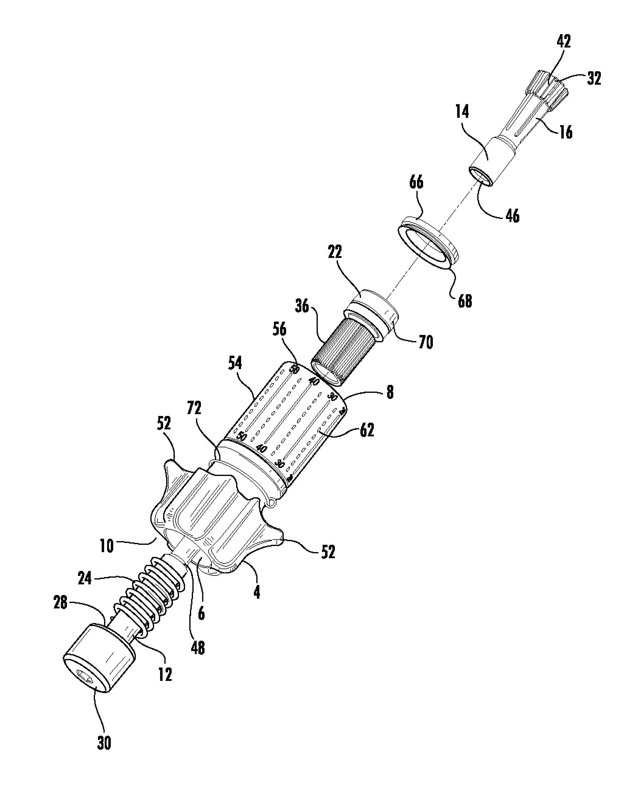
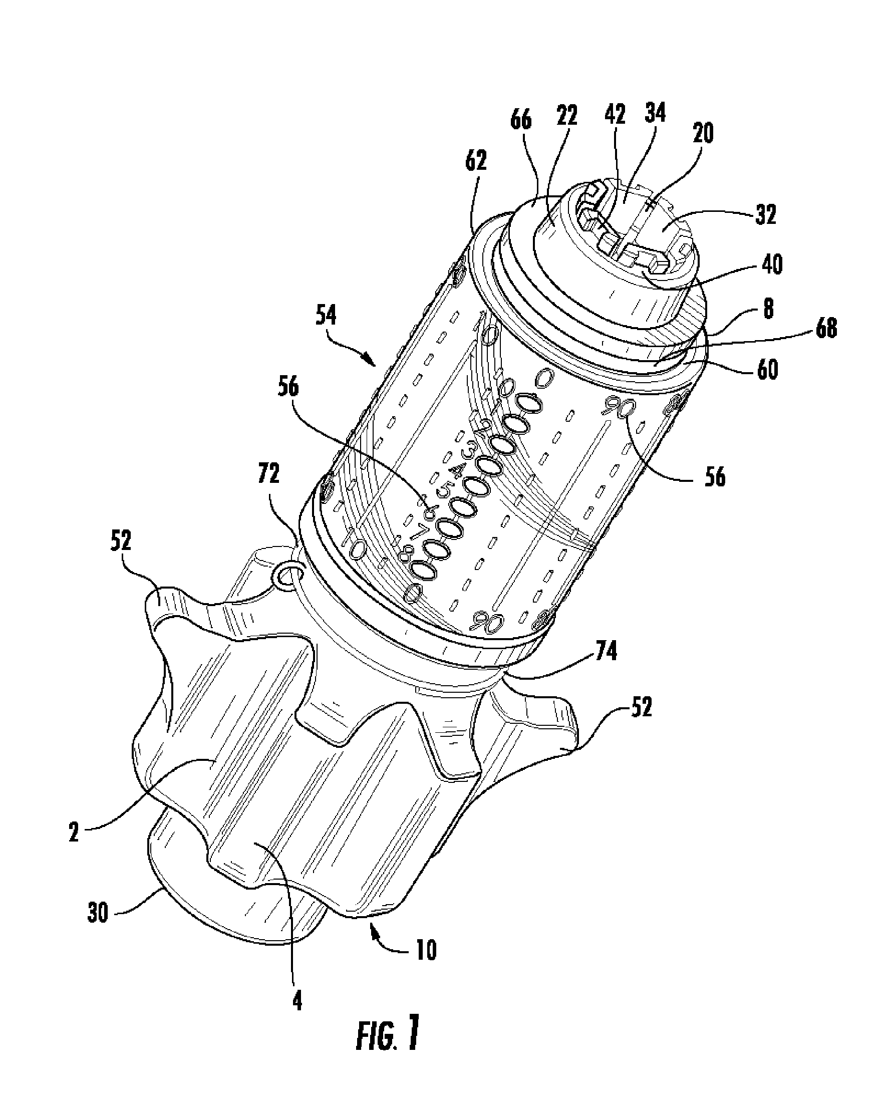
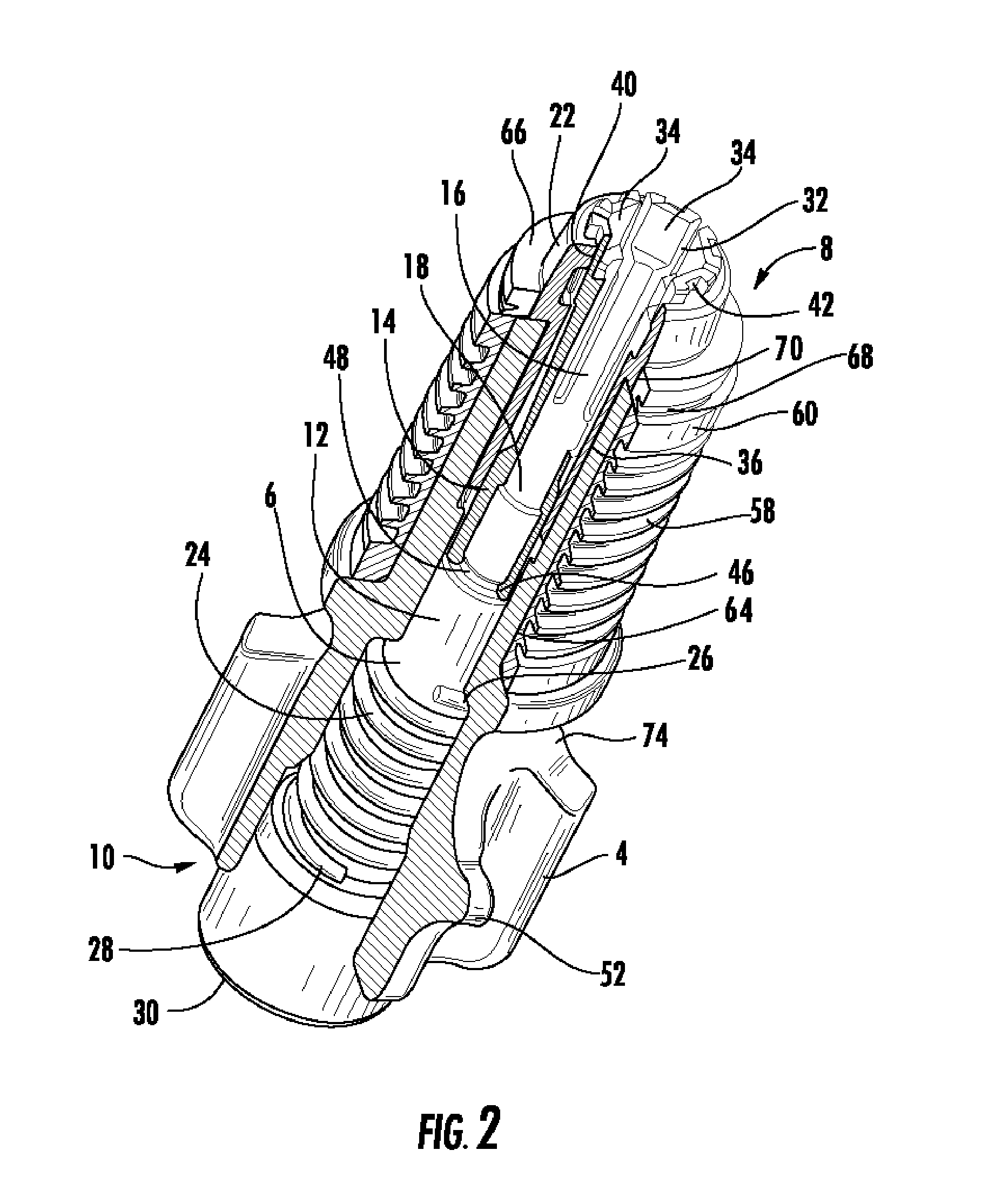
[0017]As shown in FIGS. 1-3, a first exemplary embodiment of the invention has a body 2 with exterior gripping surfaces 4 adapted for a secure grip by a typical users hand. A bore 6 between a first end 8 and a second end 10 of the body 2 carries a shaft 12. The shaft 12 has a spring finger ring 14 with a plurality of spring finger(s) 16 coupled to a tool end 18. The spring finger(s) 16 spread outward into contact with the inner surface 20 of a collet 22 coupled to the first end 8 of the body 2.

[0018]A spring 24 seated between an internal shoulder 26 of the body 2 and an external shoulder 28 proximate an actuator end 30 of the shaft 12 biases the shaft 12 toward the second end 10 of the body 2 thereby retracting the spring finger(s) 16 to a closed position.

[0019]As best shown in FIGS. 4 and 5 the body 2, collet 22 and spring finger ring 14 are adapted to key together such that rotation of the body...


PUM


Abstract

An adjustment tool, having a body with a bore extending between a first end and a second end. A shaft is positioned within the bore having a plurality of outward spreading spring fingers coupled to a tool end. A spring biases the shaft towards the second end of the body. A collet coupled to a first end of the body has an inner surface which restricts the spring fingers to a closed position as movement of the shaft towards the second end of the body retracts the spring fingers into the collet. A bubble ring may be coupled to the body. Graduated indicia associated with the bubble ring indicates rotation of the tool for entry of precise rotational adjustments.

Description

BACKGROUND OF THE INVENTION [0001]The present invention relates to hand tools, and more specifically to an adjustment tool for adjusting rotatable elements such as nuts, bolts and the like.[0002]Hand tools are commonly used to assemble and or adjust apparatus, for example reflector antennas. Fine adjustments to the antenna(s) orientation with respect to a target signal consume a significant portion of time required during antenna installation and or performance optimization. Typically these adjustments are made local to the antenna, which may be mounted in environmentally exposed locations such as the roof or exterior wall(s) of a building or atop a radio tower.[0003]Common tools such as box and or ratchet wrenches may be used, however because they are not retained upon the nut or bolt under adjustment, these tools represent a significant drop hazard. Also, individual ratchet wrench sockets may unexpectedly separate from the ratchet handle.[0004]During final fine adjustment, only a ...

Claims


Application Information

Patent Timeline
Patent Type & Authority Patents(United States)
IPC IPC(8): B25B13/28B23B5/22B23B5/34B25B13/32
CPCB25B13/48H01Q3/02Y10T279/17529
Inventor TULLOCH, TOMMYBUCHAN, STEVEDEMPSTER, RICHARDBROOKER, RALPH
Owner ASC SIGNAL CORP
Why Eureka
Try Eureka