
Anti-squirrel bird feeder

a feeder and squirrel technology, applied in the field of anti-squirrel bird feeders, can solve the problems of reducing the utility of the feeder, immature or lightweight squirrels could defeat the closure mechanism, etc., and achieve the effects of enhancing bird watching, convenient refilling, and convenient cleaning

Active Publication Date: 2007-05-22
CORONEOS DONALD L
View PDF4 Cites 25 Cited by
  • Summary
  • Abstract
  • Description
  • Claims
  • Application Information

AI Technical Summary

Benefits of technology

"The present invention provides a bird feeder apparatus that includes a telescopic-operational assemblage, a shroud assembly, and a hopper assembly. The telescopic-operational assemblage includes a hopper scale assembly and hopper attachment means. The four-bar spring assembly provides a nonlinear closure mechanism that is driven by external load forces and countered by restorative forces. The hopper assembly includes a cylindrical hopper body, a circular hopper tray, and a plurality of vertical hopper partitions. The invention also provides a partitioned hopper that allows for easy cleaning, refilling, and viewing by bird watchers. The invention also includes a conical roof or shroud cap that invites squirrels to alight on it but prevents them from entering the feeder. The invention also provides a coaxially corrugated bridge and self-aligning means to mitigate critical item stresses when excessive lateral or vertical loads are applied to the perch assembly. The invention further includes a feed tray screen to reduce waste and a four-bar spring assembly that allows for a readily available supply of feed for birds."

Problems solved by technology

Providing a source of food, however, has a tendency to attract not only birds, but other wildlife, such as squirrels and raccoons.
The reason for a heavy setting is that a light setting can result in significant closure when only a few birds are feeding, restricting access to seed, thereby diminishing the utility of the feeder.
The unsatisfactory consequence of a heavy setting, however, is that an immature or lightweight squirrel could defeat the closure mechanism.

Method used


Image

  • Anti-squirrel bird feeder
  • Anti-squirrel bird feeder
  • Anti-squirrel bird feeder

Examples


Embodiment Construction

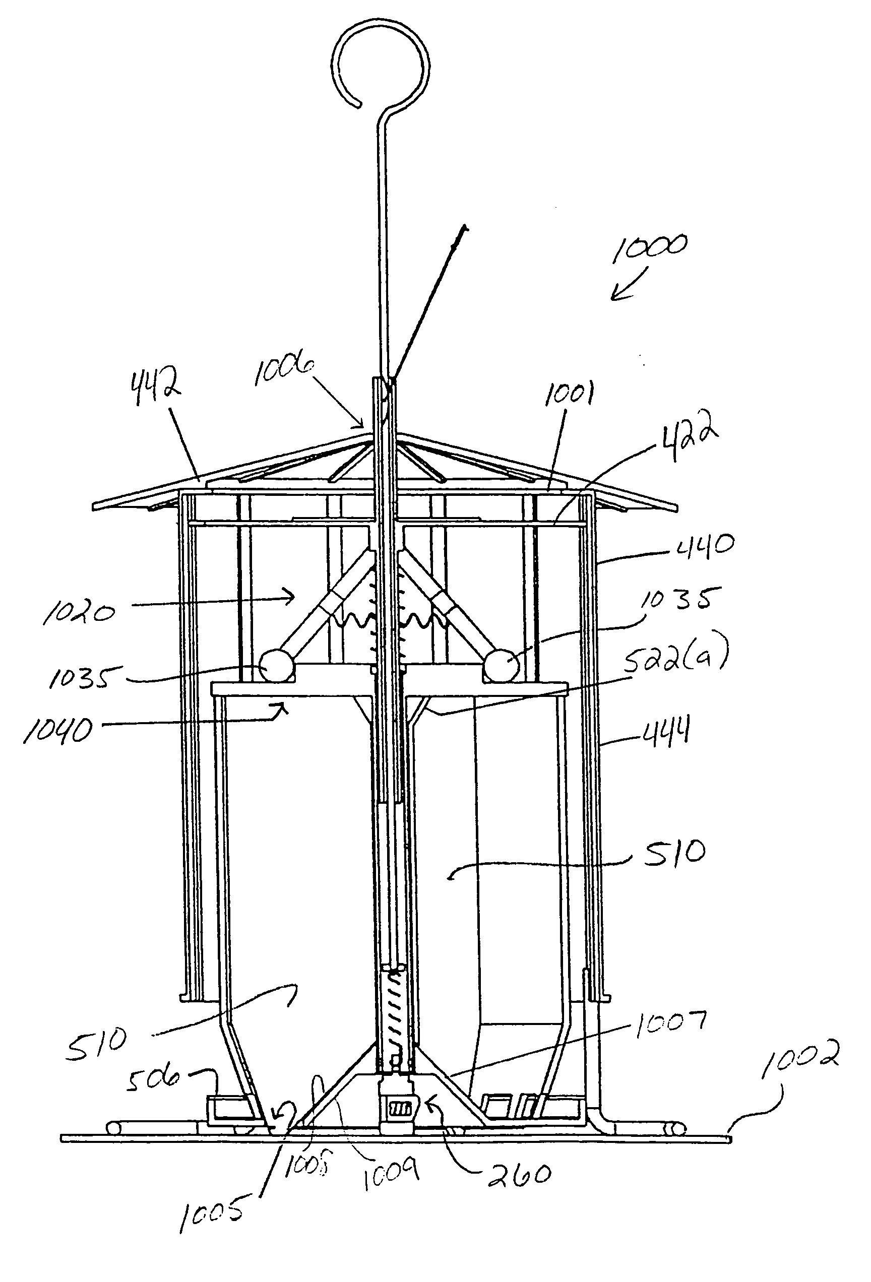
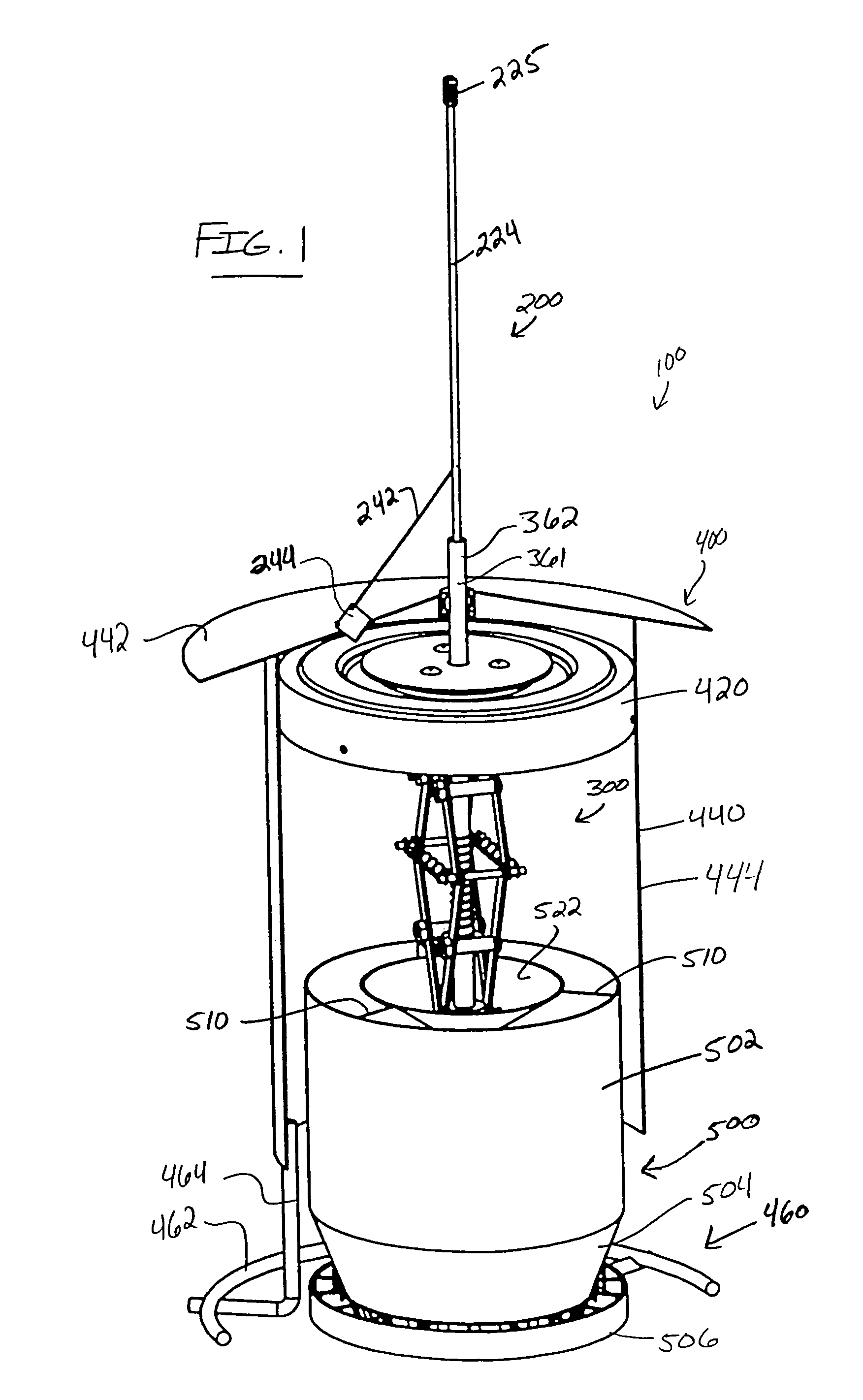
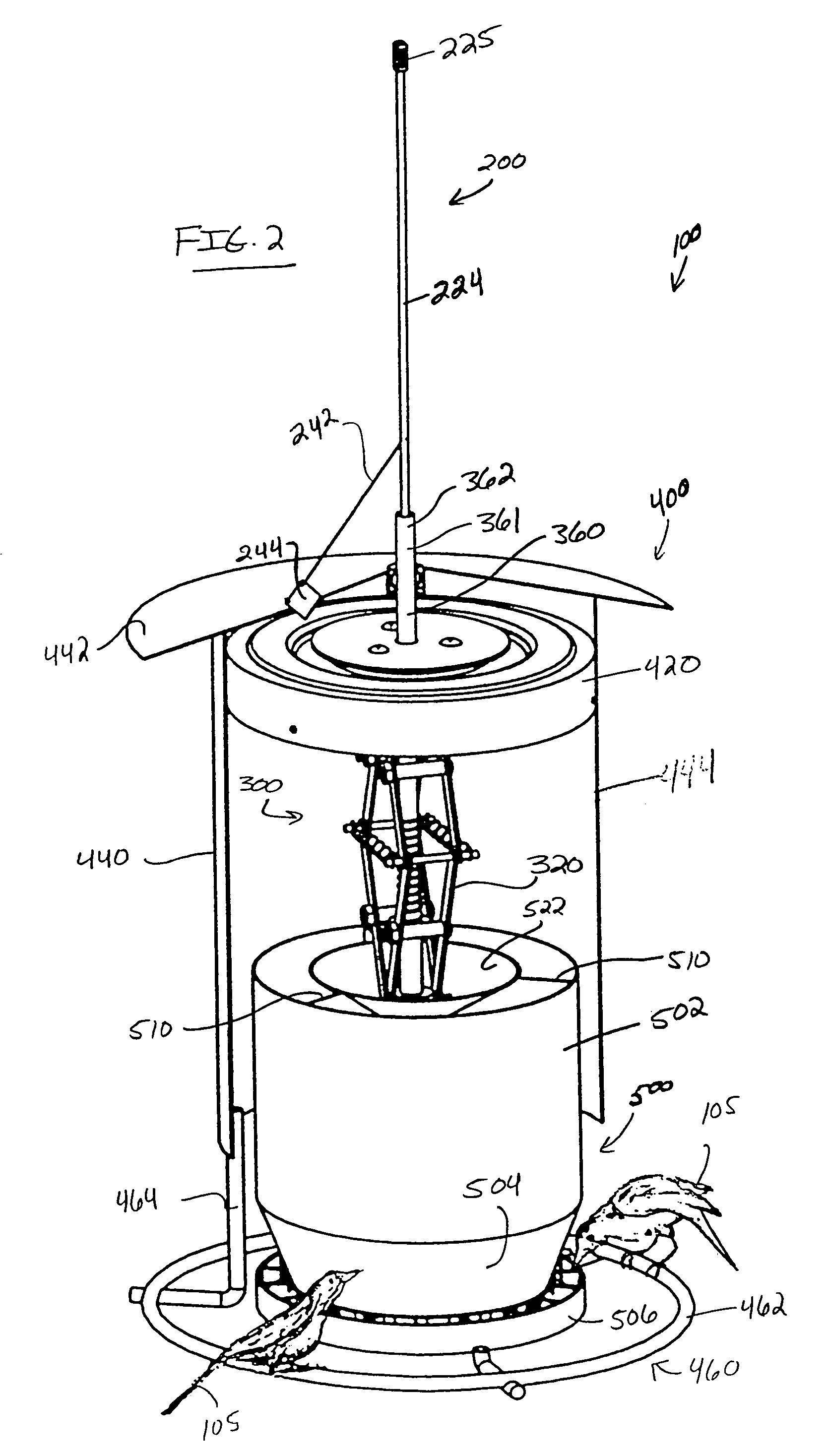
[0156]Referring now to the drawings, the preferred embodiment of the present invention concerns anti-squirrel bird feeder 100, which bird feeder 100 is generally illustrated and referenced in FIGS. 1–4, and 8(a)–8(d). Bird feeder 100 preferably comprises a number of sub-assemblies, namely, a telescopic-operational assemblage; a shroud assembly 400 as illustrated and referenced in FIGS. 1–4, 8(a)–8(d), and 28–30; and a hopper assembly 500 as illustrated and referenced in FIGS. 1–4, 8(a)–8(d), 19–27, 29 and 30. The telescopic-operational assemblage preferably comprises a support assembly 200 as illustrated and referenced in FIGS. 1–7, 8(a)–8(d), 11, and 12; and a drive assembly 300 as illustrated and referenced in FIGS. 1–5, 11, 29, and 30. Given the relatively large number of assemblies and subassemblies that comprise anti-squirrel bird feeder 100, a brief description of each assembly along with identifying reference numerals is provided directly hereunder.

[0157]Support assembly 200 ...


PUM


Abstract

The present invention provides a bird feeder apparatus for providing a readily available supply of feed for birds. The apparatus comprises a telescopic-operational assemblage, a shroud assembly, and a hopper assembly. The telescopic-operational assemblage provides a nonlinear, geometrically-based closure mechanism for effectively closing the bird feeder when a large load is placed upon the shroud assembly such as when a squirrel attempts to gain access to feed outlets of the hopper assembly by positioning itself upon the apparatus. Further, the apparatus provides a partitioned, selectively removable (drop out-type) hopper for enabling easy refills; a feed-level status flag assembly for indicating to the user whether the hopper assembly is full or empty; and at least one surround perch assembly for accommodating birds of various sizes.

Description

PRIOR HISTORY[0001]This application is a continuation-in-part patent application claiming priority to pending U.S. patent application Ser. No. 10 / 840,963, filed in the U.S. Patent and Trademark Office on May 7, 2004 now U.S. Pat. No. 6,918,353.BACKGROUND OF THE INVENTION[0002]1. Field of the Invention[0003]The present invention generally relates to a bird feeder apparatus. More particularly, the present invention relates to a bird feeder apparatus designed to provide a readily available source of feed to birds, while further functioning to prevent other small animals, such as squirrels and raccoons, from gaining access to the bird feed.[0004]2. Description of the Prior Art[0005]The study of birds is formally referred to as ornithology and within the broad compass of ornithologists is found a remarkable array of bird enthusiasts. They range from the person who notices which bird species visit the garden birdbath to the computer buff trying to mathematically describe the fate of some ...

Claims


Application Information

Patent Timeline
Patent Type & Authority Patents(United States)
IPC IPC(8): A01K61/02A01K39/01
CPCA01K39/0113
Inventor CORONEOS, DONALD L.
Owner CORONEOS DONALD L
Learn More