Piezoelectric/electrostrictive device

a piezoelectric/electrostrictive and electrode technology, applied in piezoelectric/electrostrictive transducers, generators/motors, transducer types, etc., can solve the problems of difficult high-precision (high-sensitivity, high-resolution) detection, and achieve superior response and effective prevent the damp of the vibration of the thin diaphragm portion

Inactive Publication Date: 2007-05-22
NGK INSULATORS LTD
View PDF12 Cites 10 Cited by
  • Summary
  • Abstract
  • Description
  • Claims
  • Application Information

AI Technical Summary

Benefits of technology

[0010]The present invention has been developed in view of the above-described problems, and an object is to provide a piezoelectric / electrostrictive device which is superior in response and in which high-precision (high-resolution, high-sensitivity) detection is possible, while effectively preventing damp of vibration of a thin diaphragm portion and maintaining displacement (amplitude) to be high.
[0020]According to the present invention, there is provided the piezoelectric / electrostrictive device which effectively prevents the damp of the vibration of the thin diaphragm portion and which is superior in response while maintaining the displacement (amplitude) to be high and in which the high-precision (high-resolution, high-sensitivity) detection is possible.

Problems solved by technology

Moreover, since response is lowered, there is a problem that it is difficult to perform high-precision (high-resolution, high-sensitivity) detection.

Method used


Image

  • Piezoelectric/electrostrictive device
  • Piezoelectric/electrostrictive device
  • Piezoelectric/electrostrictive device

Examples


example 1

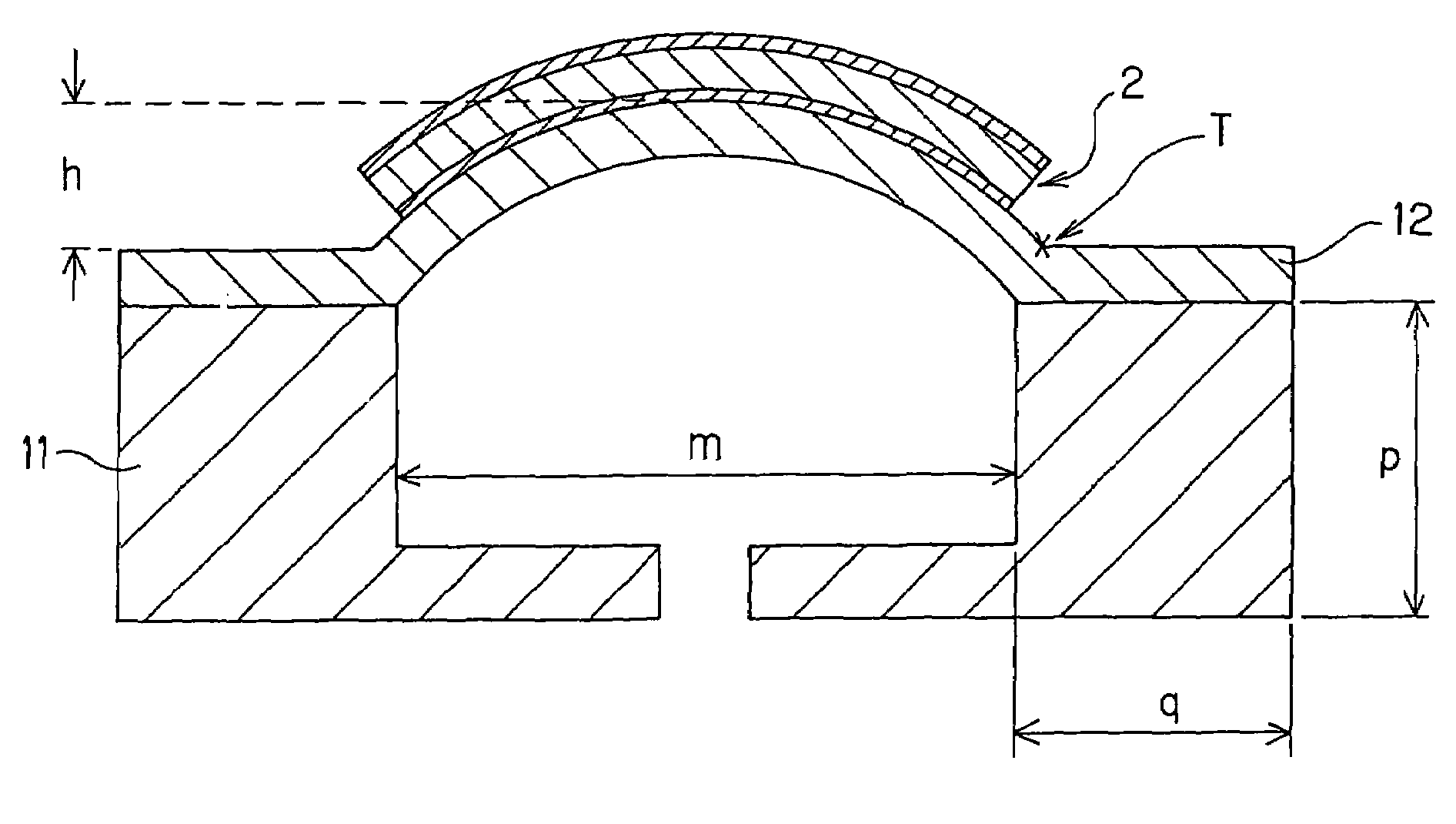
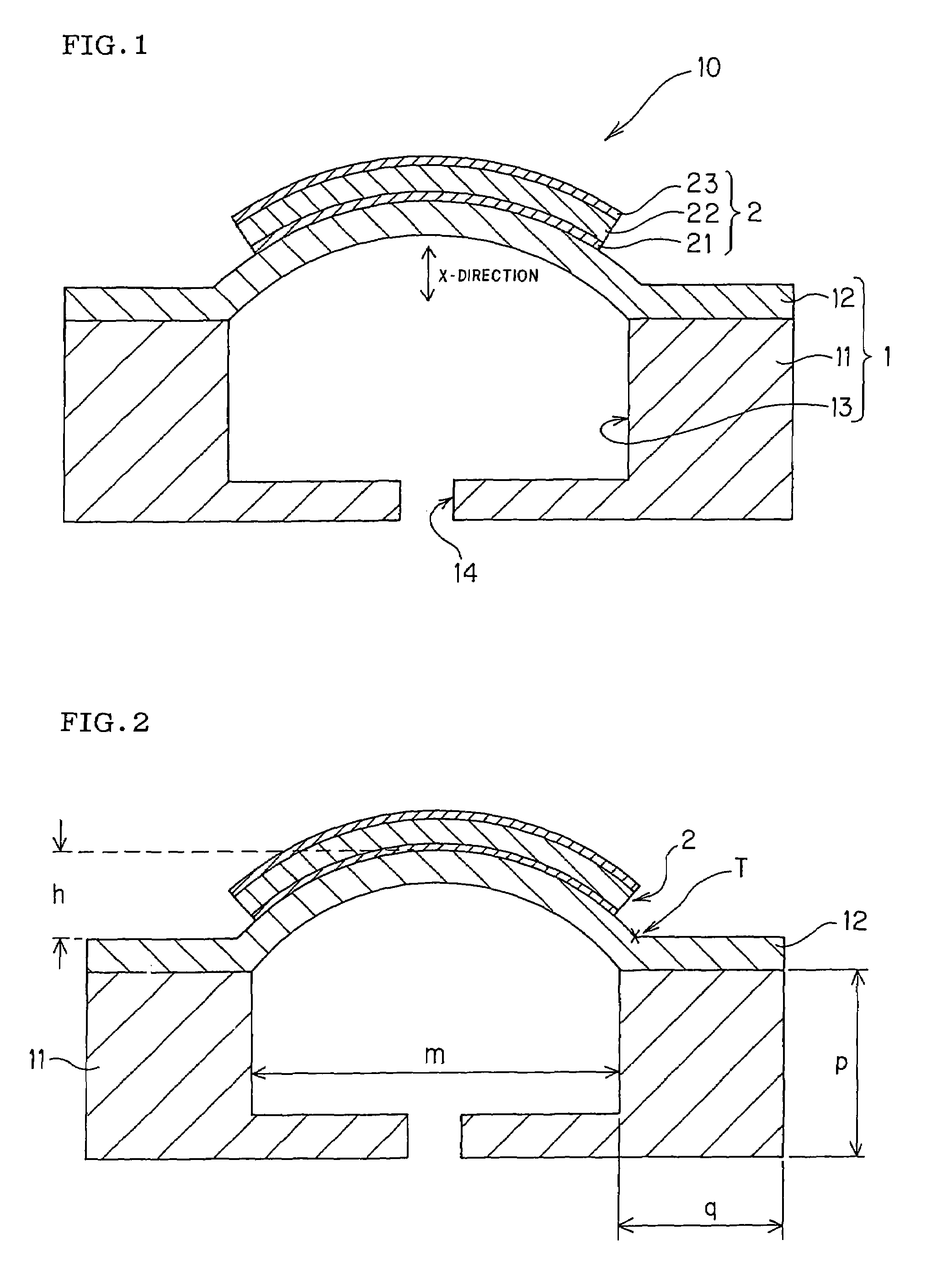
[0067]There was prepared a piezoelectric / electrostrictive device comprising one thin diaphragm portion (thickness of 14 μm, protrusion height of 20 μm, mounting width of 1500 μm), two thick portions (thick portion height of 800 μm, thick portion width of 800 μm, (height of thick portion / width of thick portion)=1.0), and one piezoelectric / electrostrictive element (lower electrode thickness of 4 μm, piezoelectric / electrostrictive film thickness of 20 μm, upper electrode thickness of 0.5 μm). It is to be noted that the protrusion height of an arch shape in the thin diaphragm portion constituting the device obtained in Example 1 was confirmed by measuring a cut surface of the piezoelectric / electrostrictive device with an optical measurement microscope.

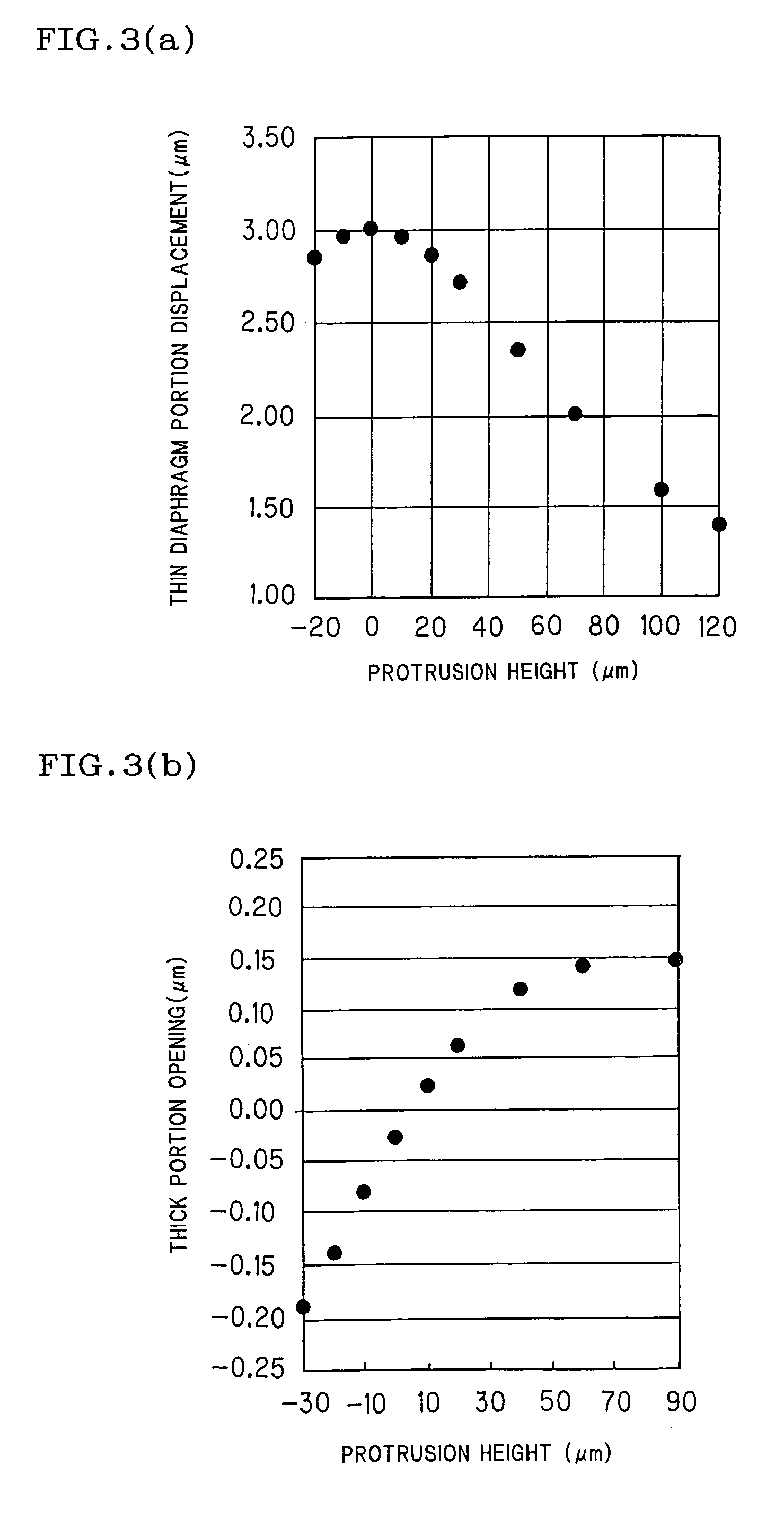
[0068](Measurement of Properties of Thin Diaphragm Portion)

[0069]As to a vibrating property in the thin diaphragm portion constituting the piezoelectric / electrostrictive device obtained in Example 1, a moment in which a voltage was interru...


PUM

PropertyMeasurementUnit
heightaaaaaaaaaa
widthaaaaaaaaaa
thicknessaaaaaaaaaa

Abstract

A piezoelectric / electrostrictive device includes: a ceramic substrate having a thick portion and a thin diaphragm portion; and a piezoelectric / electrostrictive element having a layered structure including a lower electrode, a piezoelectric / electrostrictive film, and an upper electrode, and the thin diaphragm portion of the ceramic substrate is constituted to vibrate in conjunction with the driving of the piezoelectric / electrostrictive element. Furthermore, shape and dimension relations defined in the following (A) to (C) are satisfied: (A) a shape of the thin diaphragm portion 12 is an outward protruding arch shape, and an outward protrusion height of the arch shape is in a range of 5 to 50 μm; (B) a mounting width of the thin diaphragm portion is in a range of 600 to 2000 μm; and (C) a ratio (height / width) of the height to the width of the thick portion is in a range of 0.25 to 3. According to the piezoelectric / electrostrictive device, vibration of a thin diaphragm portion is effectively prevented from being damped, and the device maintains displacement (amplitude) to be high and is superior in response and highprecision (highresolution, high-sensitivity) detection is possible.

Description

[0001]This application claims the benefit of Japanese Application No. 2004-335751, filed Nov. 19, 2004, the entirety of which is incorporated herein by reference.BACKGROUND OF THE INVENTION[0002]1. Field of the Invention[0003]The present invention relates to a piezoelectric / electrostrictive device, more particularly to a piezoelectric / electrostrictive device for use as an actuator utilizing a flexural displacement, or various types of sensors (e.g., a sensor for a microphone, a viscosity sensor, etc.) for detecting fluid properties, sound pressure, micro weight, acceleration and the like.[0004]2. Description of the Related Art[0005]A piezoelectric / electrostrictive device is used as an actuator or various types of sensors. As such piezoelectric / electrostrictive device, there is disclosed, for example, a device for use in measuring fluid properties such as density, concentration, and viscosity (see Japanese Patent Application Laid-Open No. 8-201265). Such piezoelectric / electrostrictiv...

Claims


Application Information

Patent Timeline
Patent Type & Authority Patents(United States)
IPC IPC(8): B41J2/45H01L41/09H01L41/187H01L41/193H01L41/22H01L41/314H04R17/00
CPCH01L41/098H01L41/187H10N30/2048H10N30/853
Inventor NANATAKI, TSUTOMUYOSHIOKA, KUNIHIKOYAMAGUCHI, HIROFUMI
Owner NGK INSULATORS LTD
Why Eureka
Try Eureka