Fault location using measurements from two ends of a line

a technology of fault location and measurement, which is applied in the direction of fault location, testing circuit, instruments, etc., can solve the problems of unsatisfactory achieved fault location accuracy, the inability to accurately measure the fault location accuracy of two ends, and the inability to accurately measure the fault location accuracy of one end and two ends. , to achieve the effect of avoiding the adverse influence of ct saturation on fault location accuracy

Inactive Publication Date: 2007-05-22
HITACHI ENERGY SWITZERLAND AG
View PDF11 Cites 15 Cited by
  • Summary
  • Abstract
  • Description
  • Claims
  • Application Information

AI Technical Summary

Benefits of technology

[0012]The main advantage of the fault location algorithm according to the present invention is that adverse influence of CT saturation on fault location accuracy is avoided by using post fault currents from one non-affected end as the input signals, i.e. from the end where the saturation is not detected, while utilizing post fault voltages from line terminals at both ends. Among the other advantages of the invention are that impedances of equivalent systems behind both the line ends are not required to be known; and that the form of the algorithm is compact because a first order formula has been obtained.

Problems solved by technology

However, inductive current transformers (CTs) may become saturated under transmission line faults with high fault current, which often takes place during faults close to CTs installation point.
Note that accuracy of both one-end and two-end fault locators can be adversely affected by the saturated CTs.
U.S. Pat. No. 4,559,491 which is titled Method and device for locating a fault point on a three-phase power transmission line, discloses a method and device wherein a single end fault locator uses measurements of voltages and currents from a particular side [1], and, if at the side where the fault locator is installed the CTs are saturated, the achieved accuracy of fault location could be unsatisfactory.
Using an inaccurately measured source impedance could deteriorate substantially the fault location accuracy.
The distortion of the currents, resulting from any saturated CTs, affects the accuracy of both the above two-end fault location techniques [2–3].

Method used


Image

  • Fault location using measurements from two ends of a line
  • Fault location using measurements from two ends of a line
  • Fault location using measurements from two ends of a line

Examples


Embodiment Construction

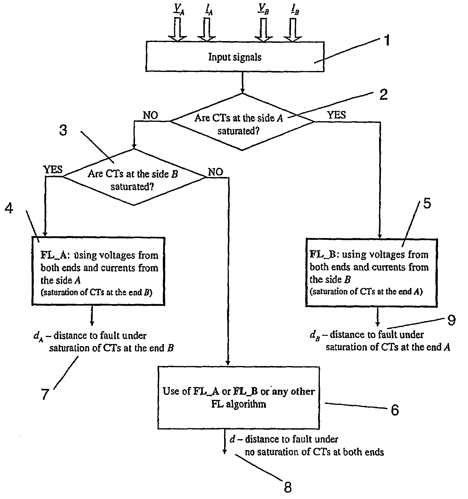
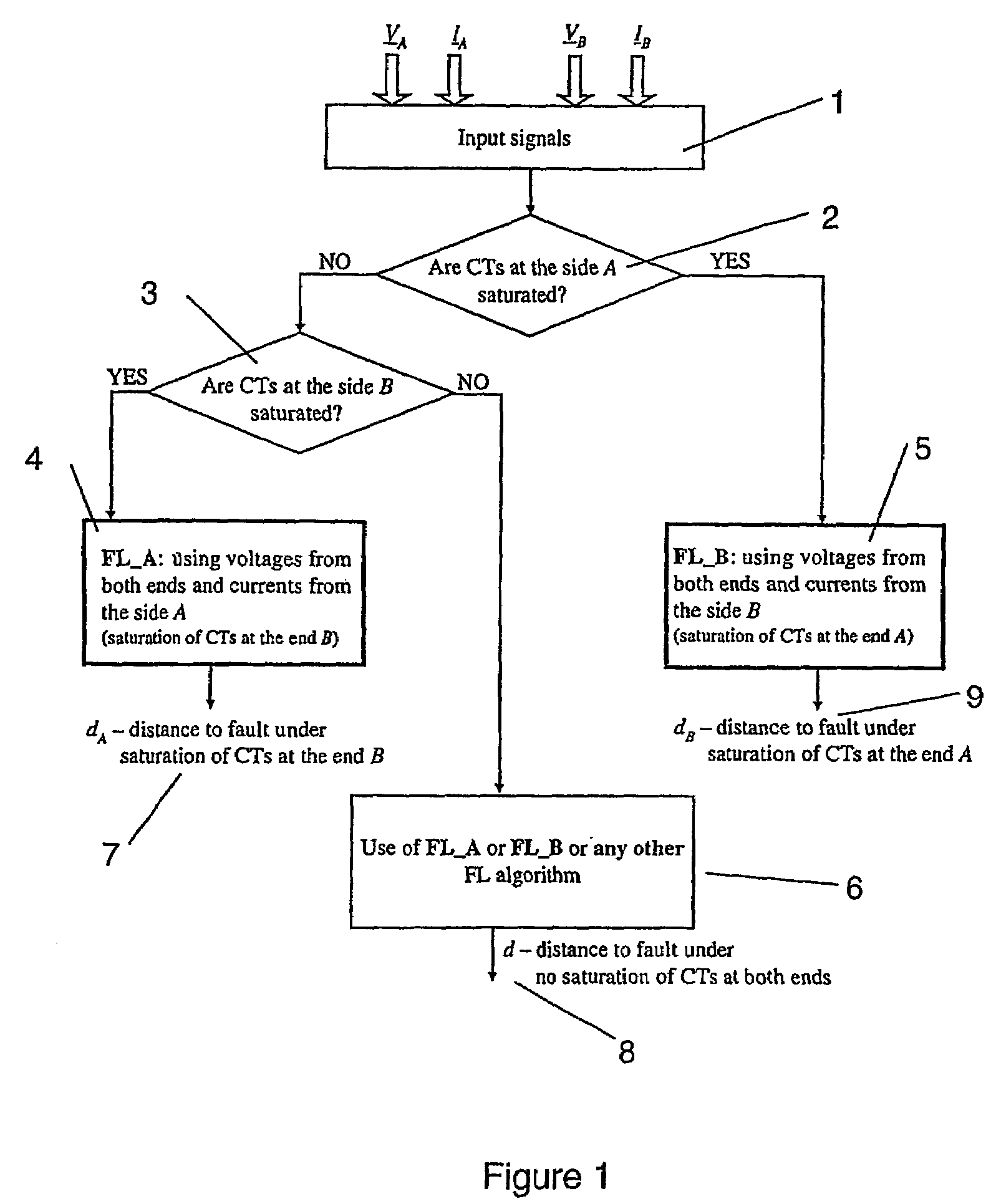
[0033]FIG. 1 shows a method in the form of a flow chart according to an embodiment of the invention. The flow chart shows means 1 for receiving input signals, a decision step 2 to determine if a CT is at one end A is saturated, and a second decision step 3 to determine whether a CT at B is or is not saturated (when step 2=Yes). A result stage 4 is shown for when Fault Location FL_A shall be used, result stage 5 when Fault Location FL_B shall be used, and result stage 6 when any Fault location algorithm including FL_A or FL_B may be used.

[0034]A determination of whether a CT is saturated or not may be carried out using a method disclosed in EP 506 035 B1 entitled Method and device for detecting saturation in current transformers, or by any other known method. The method disclosed in EP 506 035 B1 is dependent on continuously determining an absolute value of both the current and of a derivative of the current. Three criteria calculated from the measured and derived values are disclose...


PUM


Abstract

The present invention relates to a method to locate a fault in a section of a transmission line using measurements of current, voltage and angles between the phases at a first (A) and a second (B) end of said section. The invention is characterised by the steps of, after the occurrence of a fault along the section, calculating a distance (dA, dB) to a fault dependent on a fault current measured at one of said first and second ends and phase voltages measured at both of said first and second ends (A, B), where the distance to fault is calculated from the end (A or B) where the fault current is measured. The invention is particularly suitable when a current transformer at either of the first or second ends (A, B) is saturated. If so, then, a distance (d) to a fault is calculated dependent on a fault current measured at the non-affected end and phase voltages measured at both the affected end and the non-affected end.

Description

CROSS-REFERENCE TO RELATED APPLICATIONS[0001]This application claims priority to Swedish patent application 0103916-3 filed Nov. 23, 2001 and is the national phase under 35 U.S.C. § 371 of PCT / SE02 / 02144.TECHNICAL FIELD[0002]The present invention is concerned with a method and device for locating a fault on a section of a power transmission line. The method utilizes measurements of current and voltage made at relays installed at terminals at both ends of the section of the power line.BACKGROUND ART[0003]Several methods and approaches for fault location in high voltage power systems have been developed and employed. One approach has been to use voltage / current transducers located at terminals, between which the power lines to be monitored run. Inductive current transformers are used to provide a measurement of instantaneous current in a transmission line.[0004]However, inductive current transformers (CTs) may become saturated under transmission line faults with high fault current, wh...

Claims


Application Information

Patent Timeline
Patent Type & Authority Patents(United States)
IPC IPC(8): G01R31/08H02H3/40
CPCH02H3/40G01R31/088
Inventor SAHA, MURARI MOHANROSOLOWSKI, EUGENIUSZIZYKOWSKI, JAN
Owner HITACHI ENERGY SWITZERLAND AG
Why Eureka
Try Eureka