Self-oscillating switching amplifier

a switching amplifier and self-oscillating technology, applied in the field of amplifiers, can solve the problems of high distortion of switching amplifiers, difficult design of feedback loops, and natural non-linear magnetic hysteresis, and achieve the effects of high audio performance, simple circuit, and high audio performan

Inactive Publication Date: 2007-05-22
CORETRONIC
View PDF3 Cites 77 Cited by
  • Summary
  • Abstract
  • Description
  • Claims
  • Application Information

AI Technical Summary

Benefits of technology

[0010]The present invention provides a simple circuit for generating oscillation and for controlling the power switch of switching amplifiers in pulse width modulation (PWM) to achieve high audio performance. Oscillation is generated by forcing the loop phase shift to exceed 360 degrees while loop gain approaches unity. High audio performance is achieved by multiple feedbacks, with at least one of them covers the output reconstruction filter which may have its non-linearities. High frequency switching is accomplished via high speed circuits not only in the high gain section of the loop but also in the feedback circuit. Both high speed operational amplifiers and comparators are used to make switching frequency very high, in the 100–1000 Khz range and above, in spites of the low pass reconstruction filter used by necessity at the output section.
[0011]Embodiments of the invention provide, for example, methods and apparatus for controlling a power switch by PWM to provide high audio performance via high frequency self-oscillation. Certain embodiments can also provide methods and apparatus for minimizing distortion of a self-oscillating switching amplifier via multiple feedback paths. Further, certain embodiments provide methods and apparatus for controlling a power switch such that distortion of a self-oscillating switching amplifier is minimized by dynamic change of mode of switching of the power switch.

Problems solved by technology

Many other elements of a switching amplifier such as fluctuation of power supply voltages, switching delays, dead times, nonlinearities of most semiconductor components and real passive components, all contribute to relatively high distortion of switching amplifiers.
That large phase shift makes the design of the feedback loop difficult due to the possibility of oscillation when the total phase loop shift exceeds 360 degrees, taking into account the inherent 180 degrees phase shift of the negative feedback path and the error amplifier's own phase shift which reaches 90 degrees at only tens of hertz.
Magnetic hysteresis is naturally non-linear, and can be a major cause of distortion of switching amplifiers.
The need for stable feedback loop thus limits the bandwidth of typical switching amplifiers.
Some switching amplifiers that process signals only in the digital domain don't even have any feedback and suffer from distortions.
Limited bandwidth of conventional feedback for switching amplifiers thus limits their audio performance in terms of distortion.
That dominant pole in turn limits the bandwidth of linear amplifiers, and more importantly reduces their ability to attenuate distortion at high frequencies where human ears can really tell slight differences.
Indeed studies have shown that high-order harmonic distortions are not pleasing to our ears whereas low order harmonics can be tolerated because they already exist in the audio program and because they are in fact harmonious with the fundamental.
The signal inverter itself is a source of phase shift and distortion.

Method used


Image

  • Self-oscillating switching amplifier
  • Self-oscillating switching amplifier
  • Self-oscillating switching amplifier

Examples


Embodiment Construction

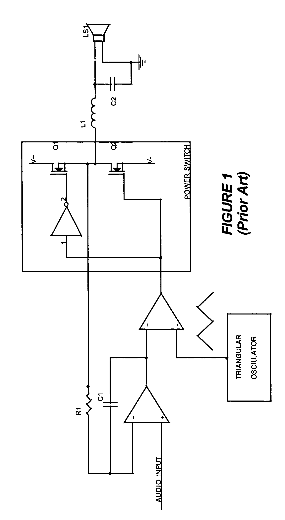
[0025]Embodiments of the present invention will now be described in detail with reference to the drawings, which are provided as illustrative examples so as to enable those skilled in the art to practice the invention. Notably, the figures and examples below are not meant to limit the scope of the present invention. Where certain elements of these embodiments can be partially or fully implemented using known components, only those portions of such known components that are necessary for an understanding of the present invention will be described, and detailed descriptions of other portions of such known components will be omitted so as not to obscure the invention. Further, the present invention encompasses present and future known equivalents to the components referred to herein by way of illustration.

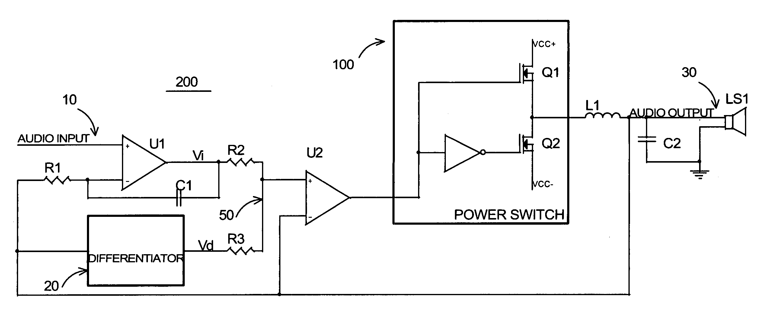
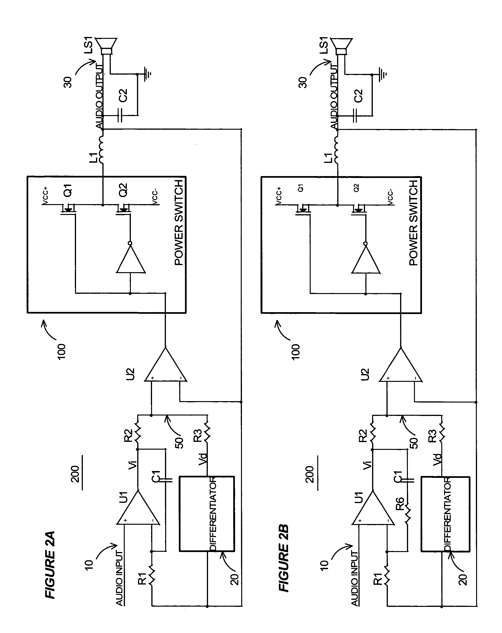
[0026]Certain embodiments of the present invention provide a self-oscillating switching amplifier comprising a power switch 100 usually composed of power MOSFETs in a half-bridge or a...


PUM


Abstract

A self-oscillating switching amplifier having an error amplifier output combined with the output of an output signal differentiator according predetermined weighing factors to force a small oscillation around the averaged output signal at a high frequency. The feedback voltage is sensed at the output of the switching amplifier. Additional feedback can be derived from a switching node of the power switch. The switching of the power switch can be dynamically changed from binary switching when the amplitude of the audio signal is low, to ternary switching when the amplitude of the input signal is high to minimize distortion of the output signal. The amplifier can be supplied with a pulsing voltage. In certain embodiments the output signal differentiator is simply a capacitor or a LC resonance circuit coupled directly to an appropriate speaker terminal for the highest possible self-oscillating frequency of the switching amplifier.

Description

CROSS-REFERENCE TO RELATED APPLICATIONS[0001]This application claims the benefit of priority to U.S. Provisional Application No. 60 / 572,548 filed May 18, 2004, and to U.S. Provisional Application No. 60 / 618,869, filed Oct. 13, 2004, both of which applications are fully incorporated herein by reference and for all purposes.BACKGROUND OF THE INVENTION[0002]1. Field of the Invention[0003]The present invention relates generally to amplifiers, and specifically to switching amplifiers.[0004]2. Description of Related Art[0005]Switching amplifiers typically generate a pulse-width modulated (PWM) waveform by comparing a triangular oscillator's waveform to the audio input signal. The linearity of the triangular waveform has a direct effect on the distortion of the audio output. Many other elements of a switching amplifier such as fluctuation of power supply voltages, switching delays, dead times, nonlinearities of most semiconductor components and real passive components, all contribute to re...

Claims


Application Information

Patent Timeline
Patent Type & Authority Patents(United States)
IPC IPC(8): H03F3/38H03F3/217
CPCH03F1/32H03F3/181H03F3/217H03F3/3022H03F2200/03
Inventor NGUYEN, TRANH T.
Owner CORETRONIC
Why Eureka
Try Eureka