Semiconductor device including a prediction circuit to control a power status control circuit which controls the power status of a function circuit

a technology of prediction circuit and function circuit, which is applied in the direction of generating/distributing signals, pulse techniques, instruments, etc., can solve the problems of exponential remarkably increase in power consumption caused by subthreshold leak current, and inability to completely correspond to the first conventional art. achieve the effect of reducing power in the circuit block, reducing power consumption, and high performan

Inactive Publication Date: 2007-05-22
RENESAS ELECTRONICS CORP
View PDF19 Cites 16 Cited by
  • Summary
  • Abstract
  • Description
  • Claims
  • Application Information

AI Technical Summary

Benefits of technology

[0018]Accordingly, it is possible to autonomously decentralize and reduce power in the circuit block. A part of the circuit block can be easily exchanged. The overall circuit block or a part of the circuit clock can be controlled so that the power is reduced.
[0019]Further, by learning, a low-power statu

Problems solved by technology

Further, according to the first conventional art, power consumption caused by a leak current is exponentially increased in accordance with the miniaturization for manufacturing.
In particular, power consumption caused by a subthreshold leak current is remarkably increased.
However, the first conventional art completely cannot correspond to the trend to increase the power PAC.
However, in this case, when a processing speed of the chip is maintained or improved, due to the necessity to set a threshold voltage of the MOST forming the chip to be low and the necessity to make a thickness of a gate oxide film of the MOST thin, the power consumption PSL caused by the subthreshold leak current and the power consumption PGL caused by the gate leak current are exponentially increased.
However, as described in the first and second conven

Method used


Image

  • Semiconductor device including a prediction circuit to control a power status control circuit which controls the power status of a function circuit
  • Semiconductor device including a prediction circuit to control a power status control circuit which controls the power status of a function circuit
  • Semiconductor device including a prediction circuit to control a power status control circuit which controls the power status of a function circuit

Examples


second embodiment

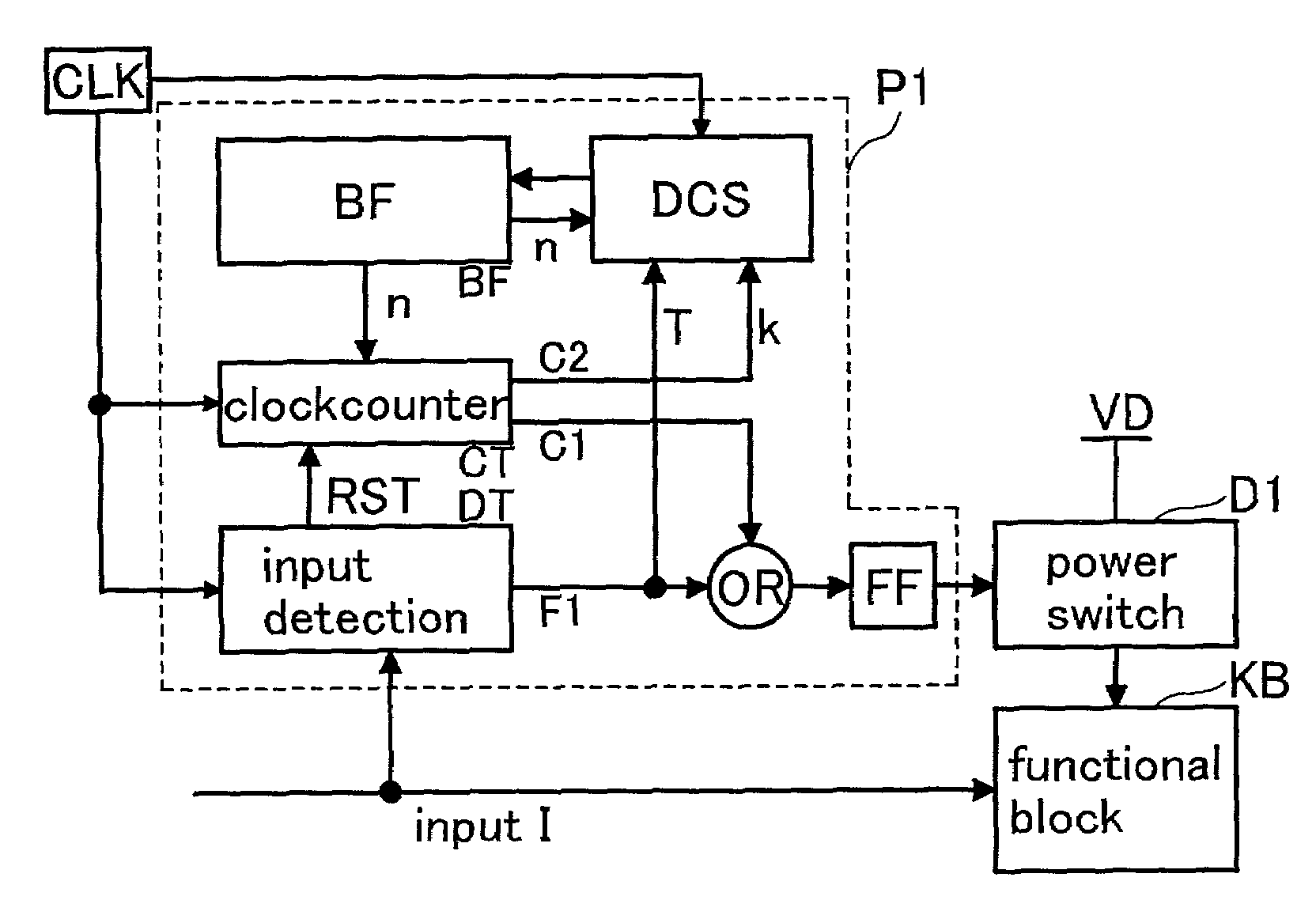
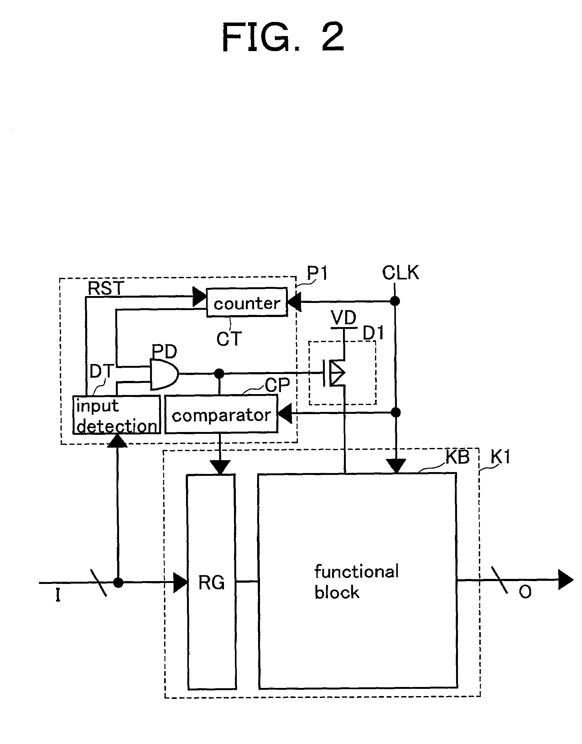
[0052]Hereinbelow, a description is given of the structure in which a functional circuit block K1 is connected to a power supply VD by using a power status control circuit D1 controlled by a prediction circuit P1 according to the present invention with reference to FIG. 2. Referring to FIG. 2, a clock CLK is inputted to the prediction circuit P1 and the functional circuit block K1. The functional circuit block K1 comprises a functional block KB for actual computation and a register RG connected to an input terminal I, for temporarily storing input information corresponding to m clocks. Incidentally, another register can be provided for an output terminal O.

[0053]The prediction circuit P1 comprises a counter CT for counting the number of clocks CLK, a controller PD for controlling the power status control circuit D1, an input detection DT for outputting a signal to the controller PD and outputting an RST signal for resetting the counter when a signal to the input I is detected and no...

third embodiment

[0075]Hereinbelow, a description is given of the structure in which power is reduced by controlling a voltage according to the present invention with reference to FIG. 3.

[0076]Referring to FIG. 3, reference symbols V1 and V2 denote voltage signal lines for applying voltages to a gate of an MOST in the power status control circuit D1. A switch (not shown) in the prediction circuit P1 selects one of the voltage signal lines V1 and V2. Based on a state of the input data to the input I and the number of clocks CLK, a switch control circuit PS determines which one of the voltage signal lines V1 and V2 is connected and when the connection is realized, thereby performing a control operation. If a voltage applied by the voltage signal line V1 is higher than a voltage applied by the voltage signal line V2, the switch in the switch control circuit PS selects the voltage signal line V1 so that the voltage is applied to the gate of the MOST in the power status control circuit D1 when the data i...

fifth embodiment

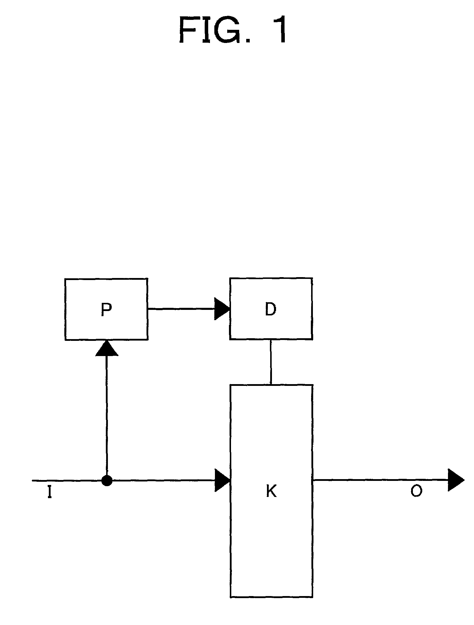
[0083]Hereinbelow, a description is given of the case in which a semiconductor device comprises a plurality of the fundamental structures of the circuits, as blocks, shown in FIG. 1, according to the present invention with reference to FIG. 5. Referring to FIG. 5, the former-stage circuit is initialized when a prediction circuit P is controlled. More specifically, in FIG. 5, a functional circuit block K-2 is started, and an REQ signal is outputted to a prediction circuit P-1, thus being in the standby mode for the initialization of a power status control circuit D-1. When the prediction circuit P-1 initializes the power status control circuit D-1 and the functional circuit block K-1 is operated, the prediction circuit P-1 returns an ACK signal to the functional circuit block K-2. The functional circuit block K-2 receives the ACK signal and, then, it transfers the data to the functional circuit block K-1. As mentioned above, the REQ signal and the ACK signal are received / transmitted ...


PUM


Abstract

A semiconductor device having a functional circuit block with predictive power controller is provided so as to construct a system LSI manufactured in a practicable number of design steps, which is extensible and in which power is reduced. The functional circuit block includes a prediction circuit and a predictive power shutdown circuit having a power status control circuit. The prediction circuit controls a power status of the functional circuit block by using the power status control circuit, based on input information thereto. When no information is inputted for a predetermined a period of time, the power status control circuit shifts from a power status of the functional circuit block to a low-power status.

Description

BACKGROUND OF THE INVENTION[0001]1. Field of the Invention[0002]The present invention relates to a semiconductor device such as a system LSI (Large-Scaled Integration) for reducing power, and more particularly, to a semiconductor device, such as a system LSI, for controlling power so that the power is autonomously decentralized to be reduced, when mounting, on a chip, various IPs (Intellectual Properties) comprising circuit blocks or circuit modules, which have various functions for the system LSI in distributional formats.[0003]2. Description of the Related Art[0004]According to a technique as disclosed in a paper of “Design Challenges of Technology Scaling” in IEEE MICRO, Vol. 19, No. 4, pp. 23–29, 1999 (hereinafter, referred to as a first conventional art), power consumption of chips for microprocessors is greatly increased and many chips having power consumption of 100W or more have been sold after 2000. Further, according to the first conventional art, power consumption caused ...

Claims


Application Information

Patent Timeline
IPC IPC(8): G06F1/32H01L27/04H03K19/00H03K19/173
CPCH03K19/0016H03K19/1735
Inventor KAWAHARA, TAKAYUKISHIMIZU, TAKEHIROARAKAWA, FUMIOMIZUNO, HIROYUKIWATANABE, TAKAOISHIBASHI, KOICHIRO
Owner RENESAS ELECTRONICS CORP
Why Eureka
Try Eureka