
Intrusion event filtering

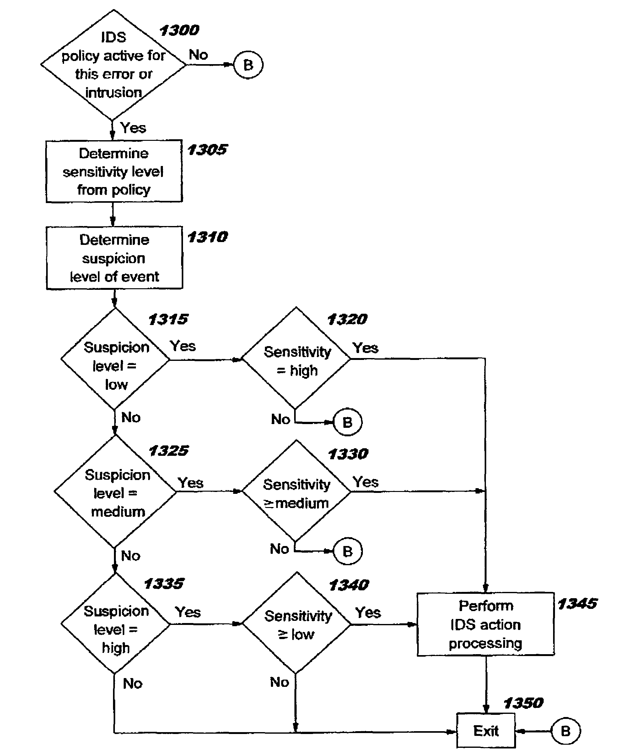
a technology of intrusion event and filtering, applied in the field of computer security, can solve the problems of business harm by rendering a network, system, or application unusable, gaining unauthorized use of a system as a stepping stone, and other attacks cannot be effectively neutralized by the target system, so as to improve computer security

Active Publication Date: 2007-05-22
TREND MICRO INC
View PDF16 Cites 126 Cited by
  • Summary
  • Abstract
  • Description
  • Claims
  • Application Information

AI Technical Summary

Benefits of technology

This approach enables real-time intrusion detection and response, reduces false positives, and supports the detection of new attacks without the need for frequent signature updates, while allowing end-to-end encryption to coexist with intrusion detection.

Problems solved by technology

It may be to cause business harm by rendering a network, system, or application unusable (referred to as “denial of service”).
Or, it may be to gain unauthorized use of a system as a stepping stone for further intrusions elsewhere.
Most intrusions follow a pattern of information gathering, attempted access, and then destructive attacks.
Other attacks cannot be effectively neutralized by the target system.
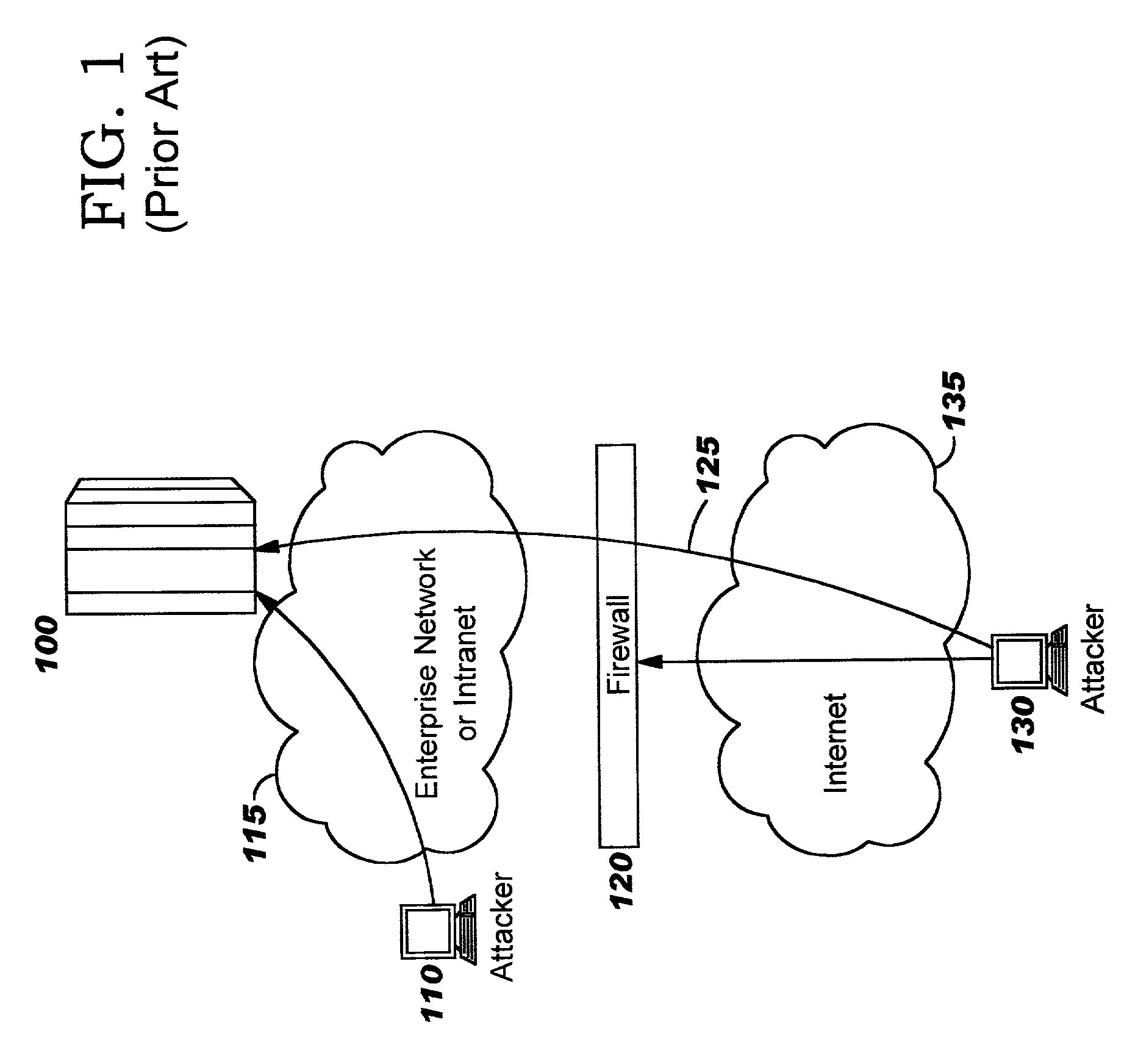
However, it cannot prevent attacks once the firewall has “approved” entry of a host into the internal network (as shown at 125), nor can it provide protection in the case where the attack is initiated from inside the network (as in the case of the attacker at 110).
In addition, end-to-end encryption limits the types of attacks that can be detected by an intermediate device such as a firewall because the intermediate device is unable to evaluate the packets in cleartext for evidence of an attack.
The network sniffers and scanners which are currently deployed have a number of limitations.
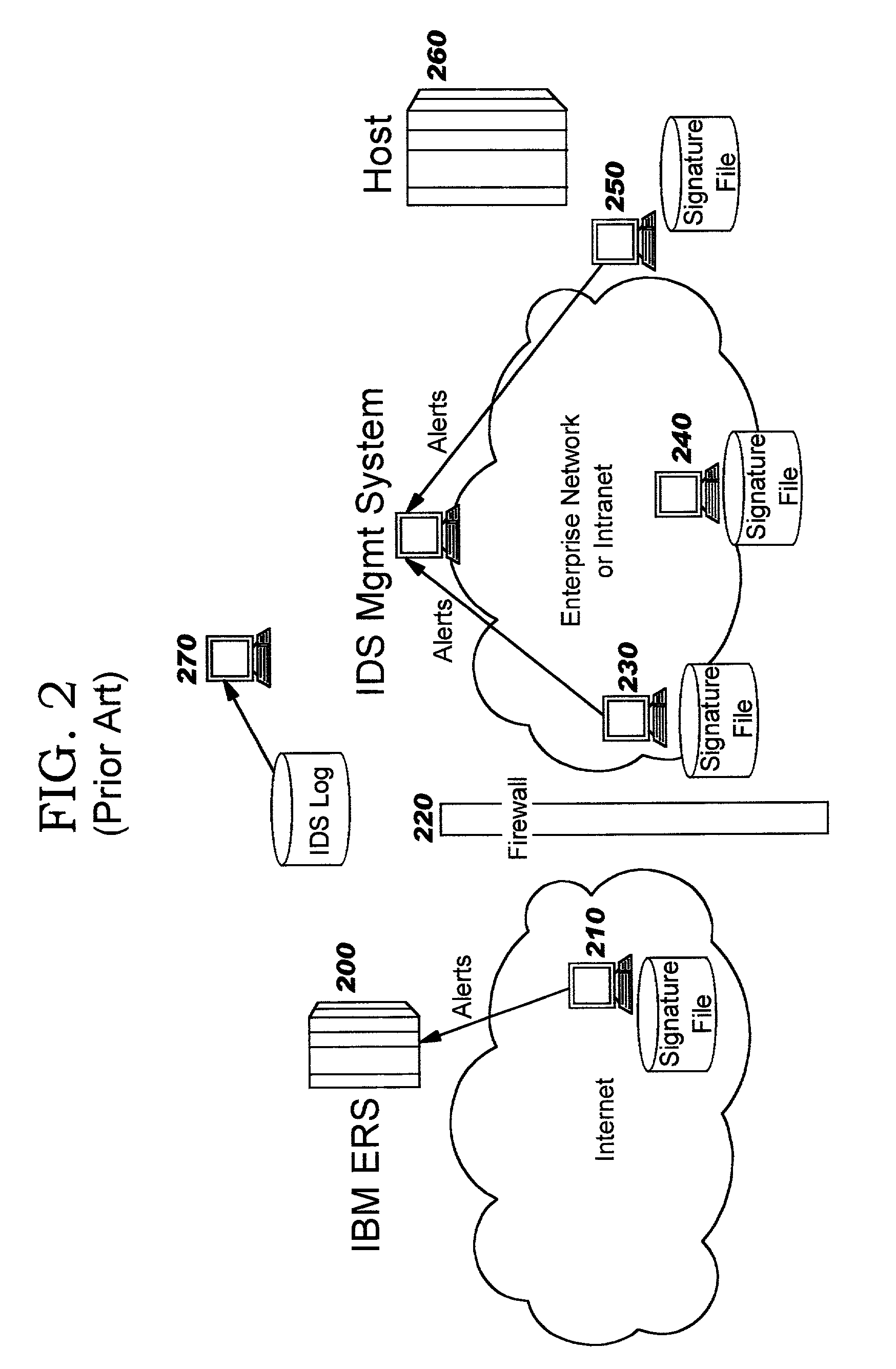
1. Network sniffers (such as elements 210, 230, 240 in FIG. 2) cannot evaluate data that is encrypted unless the sniffer and the encryption endpoint are located at the same node. Because sniffers are not typically co-located with the packet destination, providing an encryption endpoint at the sniffer is contradictory with the goal of end-to-end encryption (that is, encryption where the endpoints are the client and application server).
2. Processing signature files against every packet is very processor intensive. Many sniffers cannot process all packets, dropping packets that cannot be processed. Some installations deploy multiple sniffers, dividing the signature files into parts which are distributed to the individual sniffers. However, the ability to take real-time action in response to detecting a match against an attack signature still decreases as the backlog of traffic to analyze becomes larger.
3. Network sniffers typically cannot deflect the attacking packet or directly perform other preventative measures when an attack is detected. Thus, a damaging attack might occur even when a network sniffer detects the attack. (Sniffers and scanners typically take no direct action to stop the attacking packets, but rather notify an IDS management system. An IDS management system cannot provide a real-time reaction to prevent damage since the offending packet may reach the target system before the IDS system can respond.)
4. Scanners (such as element 270 in FIG. 2) work by evaluating logs for statistical anomalies and known attacks. Scanners have the ability to detect attacks missed by sniffers because they can react to a pattern of behavior. Because of their reliance on patterns over time, they are not real time. Furthermore, the post-processing analysis may in some cases result in “false positives”—that is, a conclusion that an attack has occurred when in reality the traffic was not attack packets.
5. Current attack signatures are written to cover single specific attacks. This results in IDSs not being able to detect new attacks until a new signature is developed and installed. Since the attack signatures are very specific, as new attacks are discovered, the signature lists can become large. As the signature lists increase, processing time at the IDS also increases, resulting in more missed attacks due to the IDS's failure to keep up with the incoming packet stream. Additionally, the IDS must be reloaded more often to pick up new signatures.
When an attack on a target system occurs, the damage may be extremely costly to repair.

Method used


Image

  • Intrusion event filtering
  • Intrusion event filtering
  • Intrusion event filtering

Examples


Embodiment Construction

[0046]The present invention defines an intrusion detection service that, in preferred embodiments, is integrated into a system or server (referred to hereinafter as a “target server” or “target system”, or equivalently as a “destination server” or “host”) that is the potential target of attack. This integrated intrusion detection service can fit into an IDS infrastructure comprised of a variety of IDS components, including IDS sensors (e.g. sniffers), scanners, analyzers, and an IDS management system. This integrated intrusion detection service preferably does not replace other IDS components in the network, but rather complements them. In fact, many security experts are proponents of using different types of IDS components (and components from different vendors) in order to have better attack coverage, drawing on the strengths of each IDS component. Thus, an implementation of the present invention may be added to an existing IDS to increase the protection afforded to an enterprise'...


PUM


Abstract

Improvements in intrusion detection are disclosed by providing intrusion event filtering and / or generic attack signature processing. These services may be integrated into a system or server that is the potential target of attack, or alternatively may be implemented in a network device. Filtering may be provided using sensitivity levels and suspicion levels. Generic attack signatures describe relatively broad classes of intrusions. Intrusion detection policy information may be used to direct the actions to be taken upon detecting an attack.

Description

RELATED INVENTIONS[0001]The present invention is related to the following commonly-assigned U.S. patent applications, all of which were filed on Dec. 5, 2001 and which are hereby incorporated herein by reference: U.S. patent application Ser. No. 10 / 007,593, entitled “Kernel-Based Security Implementation”; U.S. patent application Ser. No. 10 / 007,446, entitled “Policy-Driven Kernel-Based Security Implementation”; U.S. patent application Ser. No. 10 / 007,582, entitled “Offload Processing for Secure Data Transfer”; and U.S. patent application Ser. No. 10 / 007,581, entitled “Offload Processing for Security Session Establishment and Control”. These U.S. Patent Applications are referred to hereinafter as “the related inventions”. The present invention is also related to commonly-assigned U.S. patent application Ser. No. 10 / 058,870 (now U.S. Pat. No. 7,076,803), entitled “Integrated Intrusion Detection Services”, which was filed concurrently herewith.BACKGROUND OF THE INVENTION[0002]1. Field ...

Claims


Application Information

Patent Timeline
Patent Type & Authority Patents(United States)
IPC IPC(8): G06F11/30G06F12/14G08B23/00H04L29/06
CPCH04L63/1408
Inventor BRUTON, III, DAVID AROJAKUBIK, PATRICIALIVECCHI, PATRICK MICHAELOVERBY, JR., LINWOOD HUGH
Owner TREND MICRO INC
Learn More