Sill pan system

a technology of sliding pans and sliding doors, which is applied in the direction of snow traps, building roofs, sills/thresholds, etc., can solve the problems of affecting the performance of the system, and affecting the quality of the product. , to achieve the effect of superior abrasion resistance, less expensive, and reduced manufacturing costs

Active Publication Date: 2007-05-29
REESE ENTERPRISES +1
View PDF19 Cites 55 Cited by
  • Summary
  • Abstract
  • Description
  • Claims
  • Application Information

AI Technical Summary

Benefits of technology

[0010]In another aspect of the invention, the end pieces and central web of the pan system may be formed with a multi-ply plastic construction, especially for doorway installations. The upper surfaces of these components may be a cladding of hard abrasion resistant plastic such as, for example, polyurethane or nylon, and with the underlying substrate being made of a far less expensive plastic such as PVC. It has been found that sill pan components with such abrasion resistant upper surfaces can be even more resistant to being worn through by door units resting thereon than prior art aluminum clad sill pans. Further, the co-extrusion or co-molding of multi-ply plastic components is far less expensive and troublesome that fabricating plastic components with metal clad surfaces, as has been attempted in the prior art. The result is a superior abrasion resistant sill pan and lower manufacturing costs.
[0011]In yet another aspect of the invention, the upturned inside flange of the central web is formed to define a slot that receives and holds securely the upturned flanges on the end pieces when the ends of the web are overlapped and pressed onto the end pieces. In this way, the overlapping ends of the web are held automatically to the end pieces, eliminating the requirement that the components be held together for long periods of time while the adhesive sets. An installer need only press the ends of the web onto the end pieces, where they are held in place by the slots.
[0013]In another aspect of the sill pan system of this invention, the central web is extruded as a very long single piece. The upstanding flange along the inside edge of the web and the flashing strip along its outside edge are connected to the central portion of the web by flexible hinge joints. These hinge joints may be a co-extrusion of a flexible plastic material or may be formed by extruded score lines in the web. With such a construction, it has been found that the long single piece of web material can be rolled up into a roll with the flange and flashing strip co-extensive with the central portion of the web. For installation of a sill pan, a length of web material is extracted from the roll and cut to the precise length needed to span and partially overlap the end pieces. The inside flange and flashing strip are then simply bent respectively up and down and the central web is installed as described above. With this unique construction, multiple sill pan installations can be shipped to installers in the form of several end pieces and a roll of web material, which is more efficient, less expensive, and produces less waste than traditional sill pan systems.

Problems solved by technology

An age-old problem with window and door units is the tendency, over time, for rain water to leak beneath the sill or threshold of the unit.
Such leakage often occurs at the lower corners of the unit where the jambs meet the sill, but also can occur in mid-portions of the unit as a result of cracking or separation of sill components.
Eventually, this leakage causes the underlying framing studs and sub-floor components to rot.
Since this rot generally is hidden from view, it often is not discovered until it is so severe that major renovation to replace rotted members is required.
While prior art sill pans have been somewhat successful, they nevertheless have been plagued with a variety of problems and shortcomings inherent in their respective designs.
Single piece molded sill pans, for instance, rarely fit precisely between the vertical jambs of a framed-in opening.
This results in gaps between the ends of the sill pan and the jambs or in creases in the plastic of the pan, which can allow rainwater to seep beneath the sill pan and into the framing members below.
Multiple piece sill pans result in a good fit between the jambs, but suffer from poor adhesive coverage and thus poor seals between the ends of the center web and the end pieces, which they overlap.
Poor seals can result, in part, from the requirement in some systems that the overlapping portions be held together for 5 or more minutes as the adhesive sets.
Installers are unlikely to follow these instructions, resulting in poor and leaky adhesive joints and thus poor seals.
These poor seals allow water to seep through the adhesive joints and into the framing members below.
Further, in both of these sill pan designs, water that is intercepted by the sill pan can collect between the sill pan and the wooden sill of windows, which can result in rotting of the window sill itself.
Another problem with prior art sill pans, especially when installed beneath door units, is that the constant jostling of the threshold of the door unit as it is repeatedly stepped on during use can wear through the material of the pan at locations where the door unit rests on the pan.
This solution, however, is expensive, not always successful, and can result in an unpleasant clicking sound when stepping upon the threshold.

Method used


Image

  • Sill pan system
  • Sill pan system
  • Sill pan system

Examples


Embodiment Construction

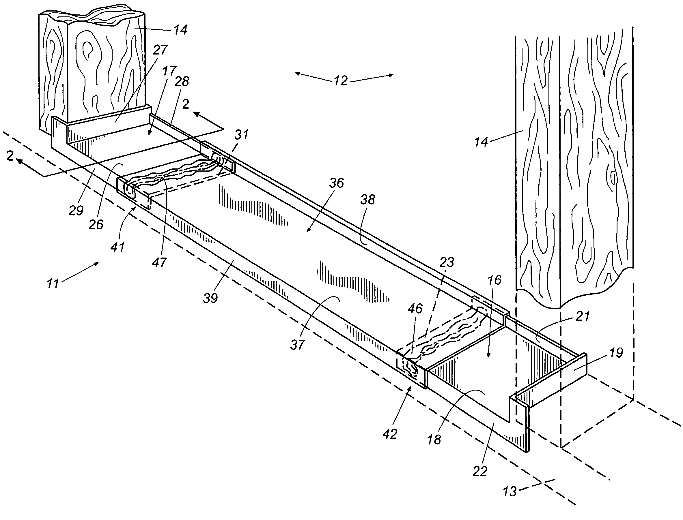
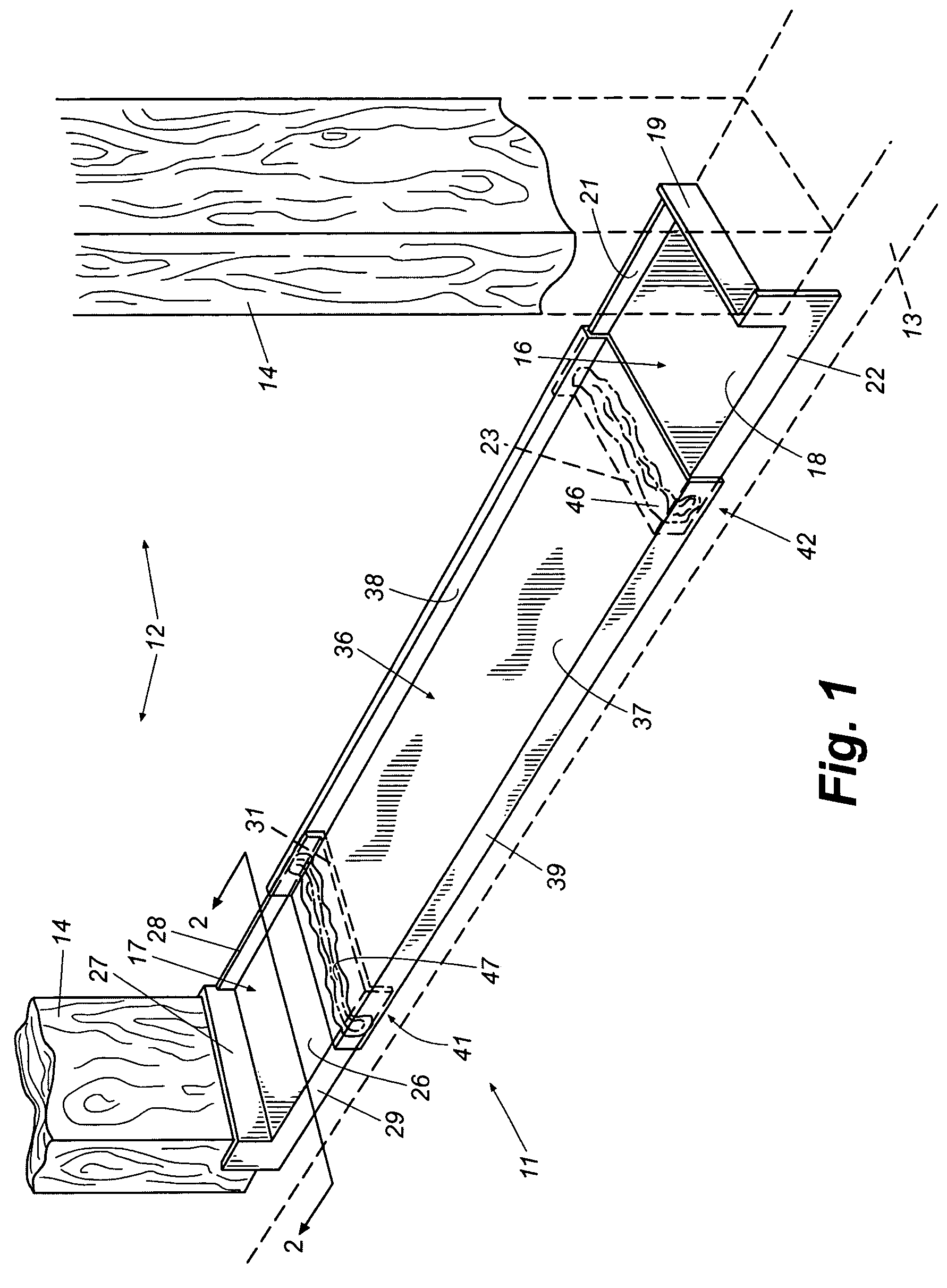
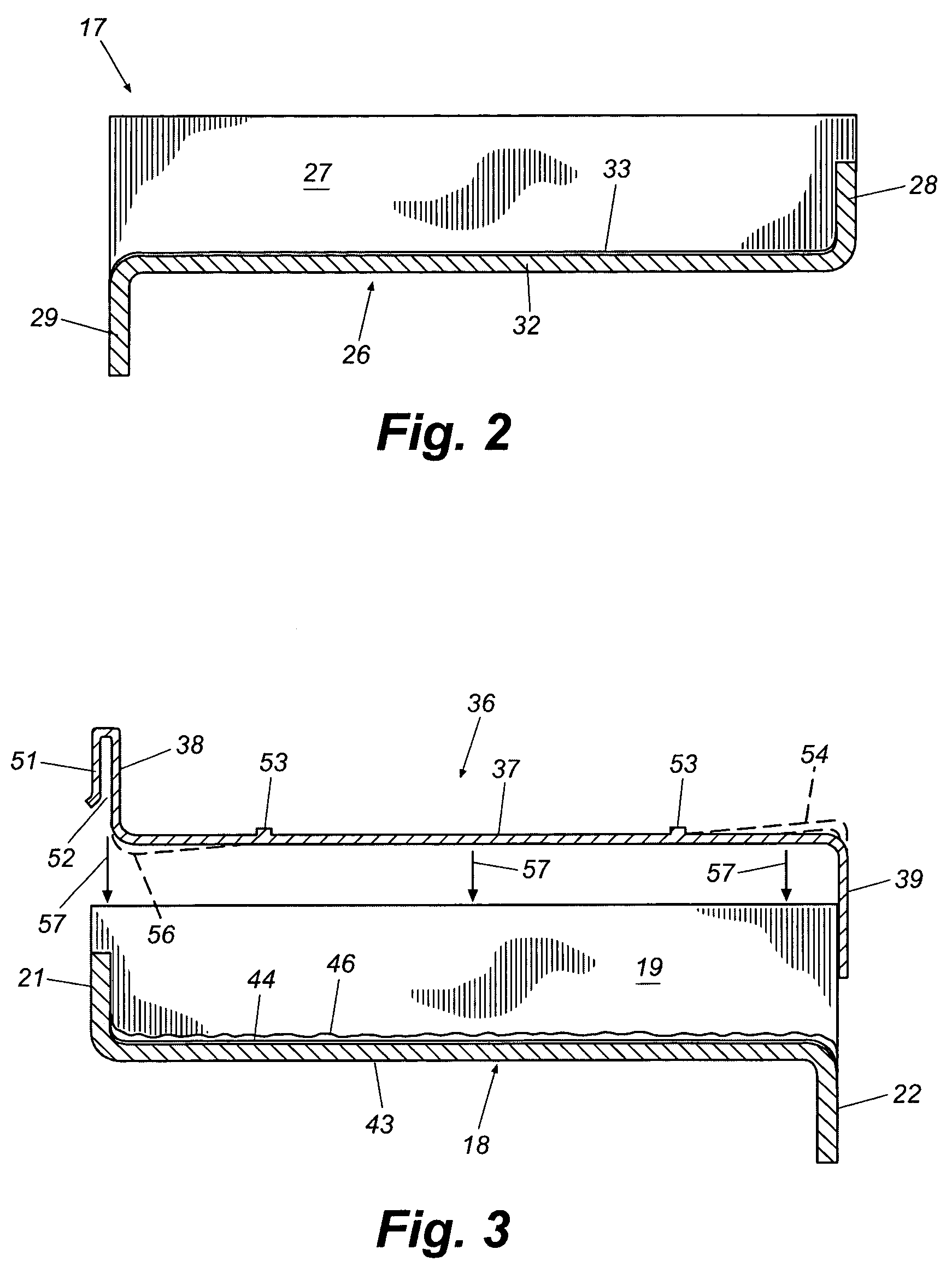
[0021]Referring now in more detail to the drawing figures, wherein like numerals refer, where appropriate, to like part throughout the several views, FIG. 1 illustrates a sill pan system that embodies principles of the invention in a preferred form. The sill pan system 11 is shown installed in a framed-in opening 12 of a building structure. The framed-in opening 12 may be a window opening or a door opening and, in the illustrated embodiment, is defined by a sill plate 13 and a spaced pair of vertical studs 14. A horizontal header (not shown) defines the upper perimeter of the framed-in opening. If the framed-in opening is a window opening, the sill plate 13 may be defined by a horizontally extending stud. Alternatively, if the framed-in opening is a door opening, the sill plate generally will simply be part of the subfloor of the building structure. In either case, the sill pan system 11 of this invention is installed in the framed-in opening between the bottom end portions of the v...


PUM


Abstract

A sill pan system is provided for installation along the bottom plate of a framed-in window or door opening to prevent water leakage. The system includes end pieces that are fitted in the bottom corners of the opening and a central web that spans, partially overlaps, and is adhered to the end pieces. The central web is formed of a transparent or translucent plastic to allow visual confirmation that a good seal is formed between the overlapping portions of the web and end pieces. The web is formed with inside flanges and flashing strips that are connected with flexible hinges so that web material can be rolled into a roll. The components may be formed with an abrasion resistant upper surface cladding and the central web may be formed with longitudinally extending drain channels for directing water to the ends of the pan for drainage.

Description

TECHNICAL FIELD[0001]This invention relates generally to window and door installations and more particularly to sill pans installable beneath window and door units to prevent water migration into underlying framing and sub-flooring.BACKGROUND[0002]In modern construction, window and door systems generally are provided as integral pre-hung units that include door or window panels pre-mounted in a frame. The frame typically is formed by vertical jambs, a top header, and a bottom sill or threshold assembly that spans the bottom ends of the jambs. These pre-hung units are fitted and secured within appropriately sized framed-in openings in the walls of a building. In the case of windows, the openings generally are framed by a horizontal bottom sill plate, vertical studs, and a header. Framed-in openings for pre-hung door units also include vertical studs and a header, but the bottom sill plate of the door opening usually is formed by the sub-floor of the building. In either event, the pre...

Claims


Application Information

Patent Timeline
Patent Type & Authority Patents(United States)
IPC IPC(8): E04D13/14E06B1/70
CPCE06B1/70E06B1/705
Inventor ELLINGSON, ROBERT T.
Owner REESE ENTERPRISES
Why Eureka
Try Eureka