Internal post flow control

a flow control and post-flow technology, applied in the direction of volume/mass flow by differential pressure, process and machine control, instruments, etc., can solve the problems of insufficient importance of flow control under varying line pressure to warrant a control responsive to pressure variations, increase flow rate, and decrease rate, etc., to achieve constant flow, reduce control gap, and increase thickness

Active Publication Date: 2007-05-29
VERNAY LAB
View PDF33 Cites 18 Cited by
  • Summary
  • Abstract
  • Description
  • Claims
  • Application Information

AI Technical Summary

Benefits of technology

[0012]In accordance with another aspect of the present invention, the annular flexible member includes an outer peripheral portion and the outer peripheral portion is of greater thickness than the inner edge. The outer peripheral portion of the annular flexible member is typically retained in a housing while the inner edge is free to deflect axially when subjected to a certain threshold pressure flow. The term “retained” as used herein refers to the outer portion being disposed in the housing such that it is not displaced during fluid flow. Accordingly, in accordance with certain aspects of the invention there may be a small clearance between the flexible member and the housing such that the flexible member cannot fall out of position. The flexible member may be free to move naturally other than being supported from downstream by a downstream portion of the housing. Deflection of the inner edge of the annular flexible member in the axial direction changes the control gap defined by the inner edge and the outer periphery of the internal post. Typically, the control gap is reduced as the pressure increases to thereby provide a relatively constant flow. The precise shape of the central post, the size of the passage channel defined by the inner edge of the annular flexible member and the shape and flexibility of the flexible member can be modified to provide controlled flow over a wide range of pressures.

Problems solved by technology

It should be noted, however, that devices of this type merely adjust the flow rate for a given line pressure, but fail to provide for pressure variations that may occur, so that if pressure increases with a device of this type, the flow rate will also increase, and conversely, should the line pressure decrease the flow rate will decrease.
In the particular applications shown in the above-noted patents, flow control under varying line pressure may not be of sufficient importance to warrant a control responsive to pressure variations.
Conventional flow control valves typically have a relatively limited range of pressures over which the control will regulate flow.
It has proven difficult to devise the appropriate geometry to achieve the desired flow control over a wide range of pressures.

Method used


Image

  • Internal post flow control
  • Internal post flow control
  • Internal post flow control

Examples


Embodiment Construction

[0018]All documents cited are, in relevant part, incorporated herein by reference; the citation of any document is not to be construed as an admission that it is prior art with respect to the present invention.

[0019]The embodiment disclosed below is not intended to be exhaustive or limit the invention to the precise form disclosed in the following detailed description. Rather, the embodiment is described so that others skilled in the art may utilize its teachings, but represents only certain manifestations of the invention.

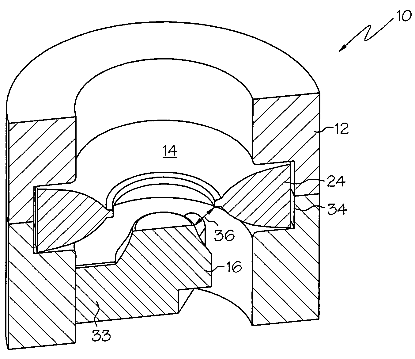
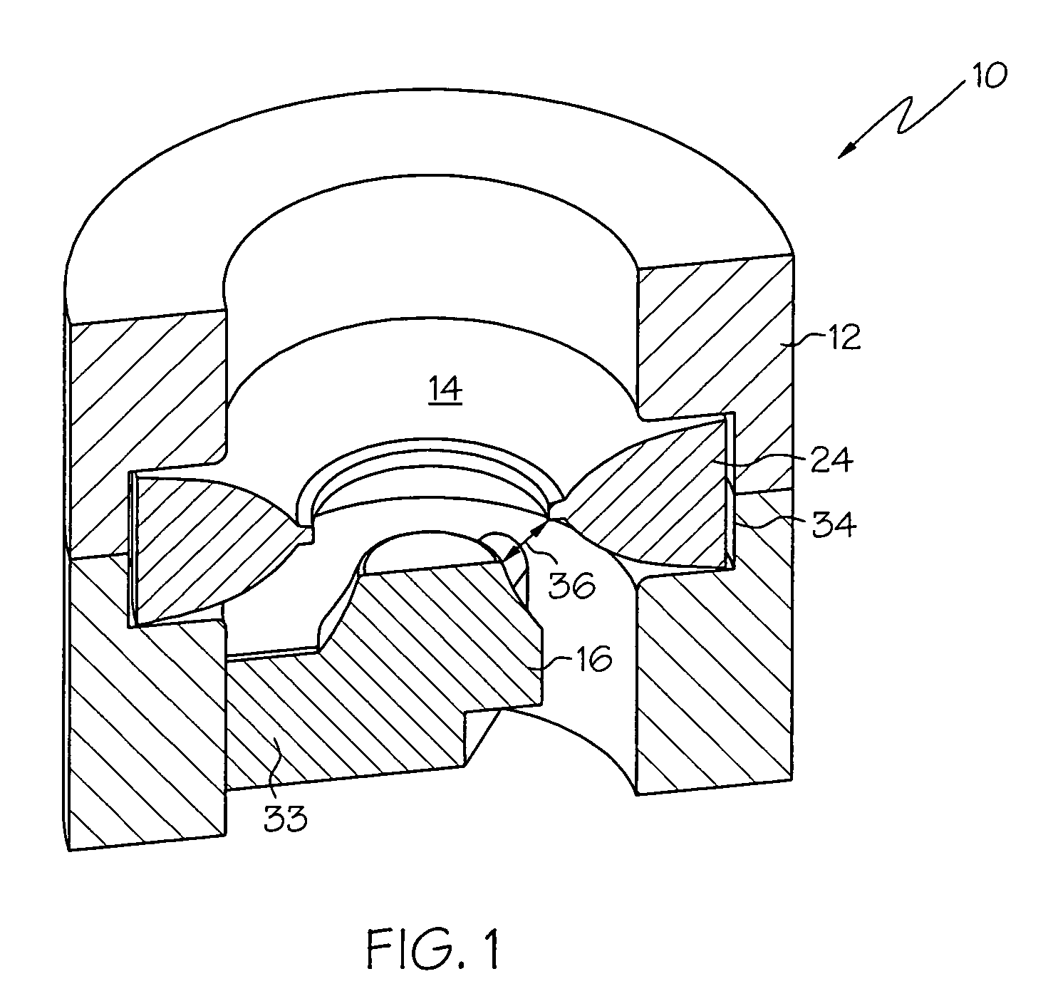
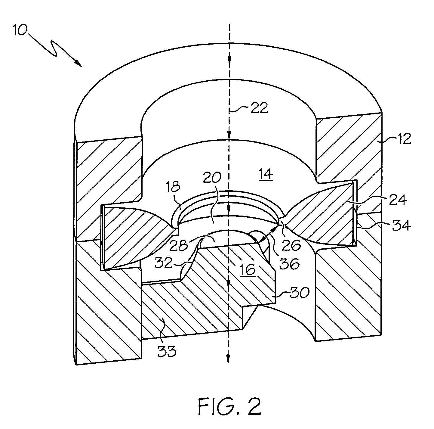
[0020]Referring to FIG. 1, the flow control assembly is indicated generally at 10 and includes a housing 12, an annular flexible member 14 and an internal control post 16. The annular flexible member 14 includes a deflectable inner edge 18 which defines a passage channel 20. The passage channel 20 extends axially along a central longitudinal axis 22 of the flow control assembly 10. The cross-section of the passage channel 20 varies along the central longitudinal a...


PUM


Abstract

A flow control including an annular flexible member and an internal post disposed downstream of the flexible member is described. The annular flexible member has a deflectable inner edge that defines a passage channel and the annular flexible member and internal post define a control gap therebetween wherein the deflectable inner edge of the annular flexible member deflects axially under increasing fluid pressure to reduce the control gap and consequently control fluid flow.

Description

BACKGROUND OF THE INVENTION[0001]The present invention relates to a flow control device, and in particular to a flow control device which has an internal post in a passage channel which, in cooperation with an annular flexible member defines a control gap between the annular flexible member and the outer peripheral surface of the internal post to provide flow control under a range of pressures.[0002]Devices for controlling the rate of flow of a fluid, primarily liquids, at varying line pressures, are utilized in a variety of applications, such as clothes washers and dishwashers, showers, faucets and plumbing valves, drinking fountains, ice makers, water softeners, automotive heating systems, fuel systems, water cooled equipment and heat exchangers, gas valves, pneumatic machine tools, respiratory controls, and water sprinklers.[0003]One device capable of providing effective control for this wide variety of installations is a rubber flow control washer, which can be routinely enginee...

Claims


Application Information

Patent Timeline
Patent Type & Authority Patents(United States)
IPC IPC(8): F16L55/02G05D7/01
CPCG05D7/0106
Inventor BAILEY, JAMES CHRISTOPHER
Owner VERNAY LAB
Why Eureka
Try Eureka