Elevator arrangement

a technology for elevator cars and brake equipment, which is applied in the direction of instruments, measurement devices, force/torque/work measurement apparatus, etc. it can solve the problems of inability to detect the operation of the brakes and injuries to passengers, so as to reduce the risk of uncontrolled starting and improve safety. , the effect of saving the energy consumption of the elevator

Active Publication Date: 2007-05-29
KONE CORP
View PDF10 Cites 37 Cited by
  • Summary
  • Abstract
  • Description
  • Claims
  • Application Information

AI Technical Summary

Benefits of technology

[0014]In an embodiment of the invention, the testing situation is repeated automatically at prescribed intervals when the elevator is empty. Start-up situation refers e.g. to installation of the elevator or renewal of the electrification system of the elevator. Start-up situation also refers to regular maintenance during which the measurement of the torques is performed. A start-up situation and the associated measurements of the first and second torques are started e.g. by means of a user interface separately connected to the control system. In this way, the control system can distinguish between situations where the elevator is loaded with a test weight and situations where the elevator is empty for measurement of the second torque.
[0018]The advantages of the invention are related to improved safety. Checking the condition of the brakes at regular intervals even outside maintenance visits considerably reduces the risk of uncontrolled starting. In addition, regular measurement of the torque required for moving the elevator car at normal speed brings savings in the energy consumption of the elevator because a partly blocked brake can not necessarily be detected without an accurate torque measurement.

Problems solved by technology

Sudden stops occurring even with a relatively low kinetic energy may cause injuries to passengers.
In the case of variable-speed elevators employing electronic adjustment, operativeness of the brakes can not be so easily detected because the brakes do not necessarily have a significant effect on stopping accuracy.
It is additionally possible that the elevator serviceman adjusts the brakes incorrectly to reduce the disturbing noise produced by the brakes.

Method used


Image

  • Elevator arrangement
  • Elevator arrangement
  • Elevator arrangement

Examples


Embodiment Construction

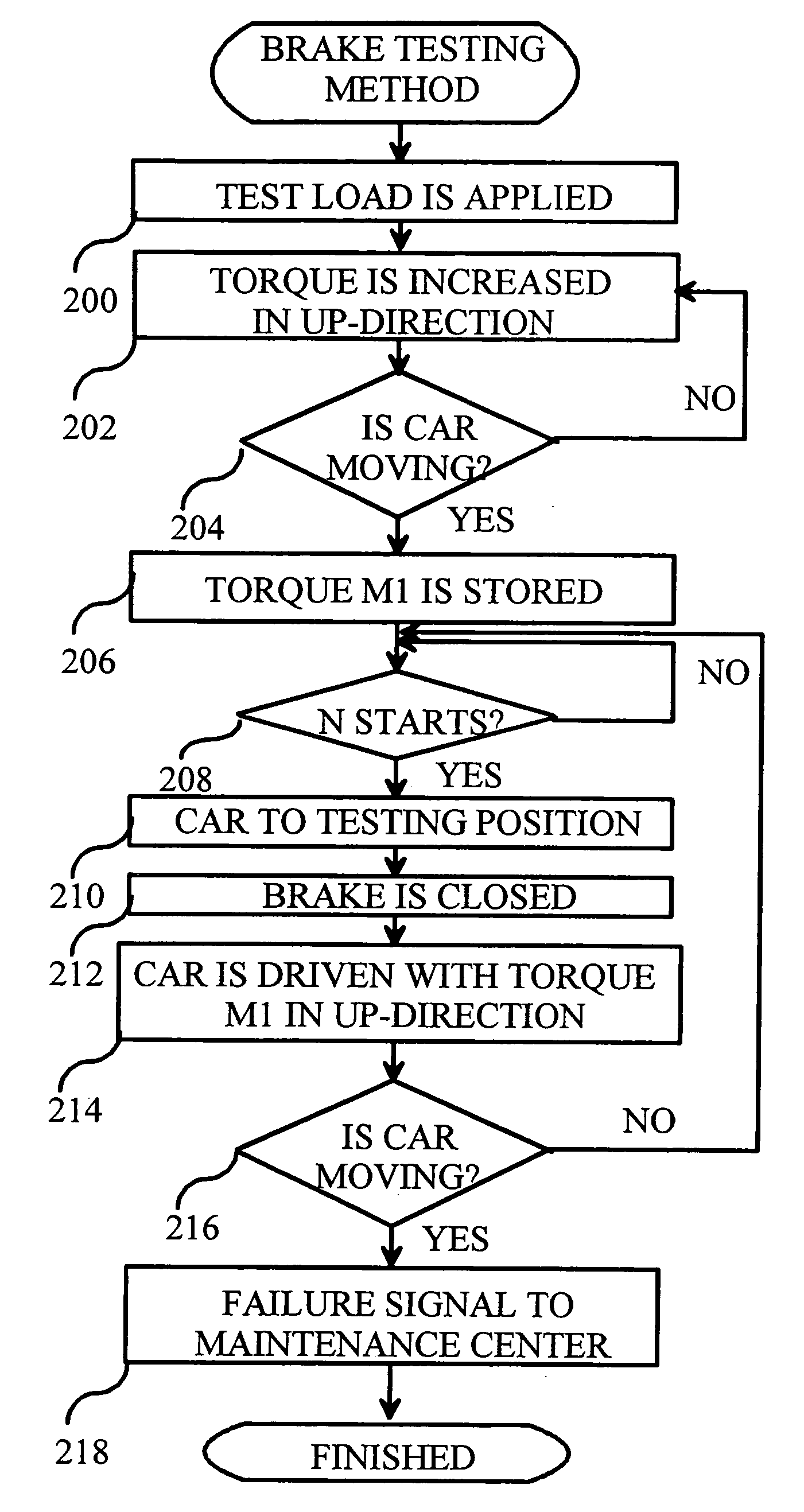
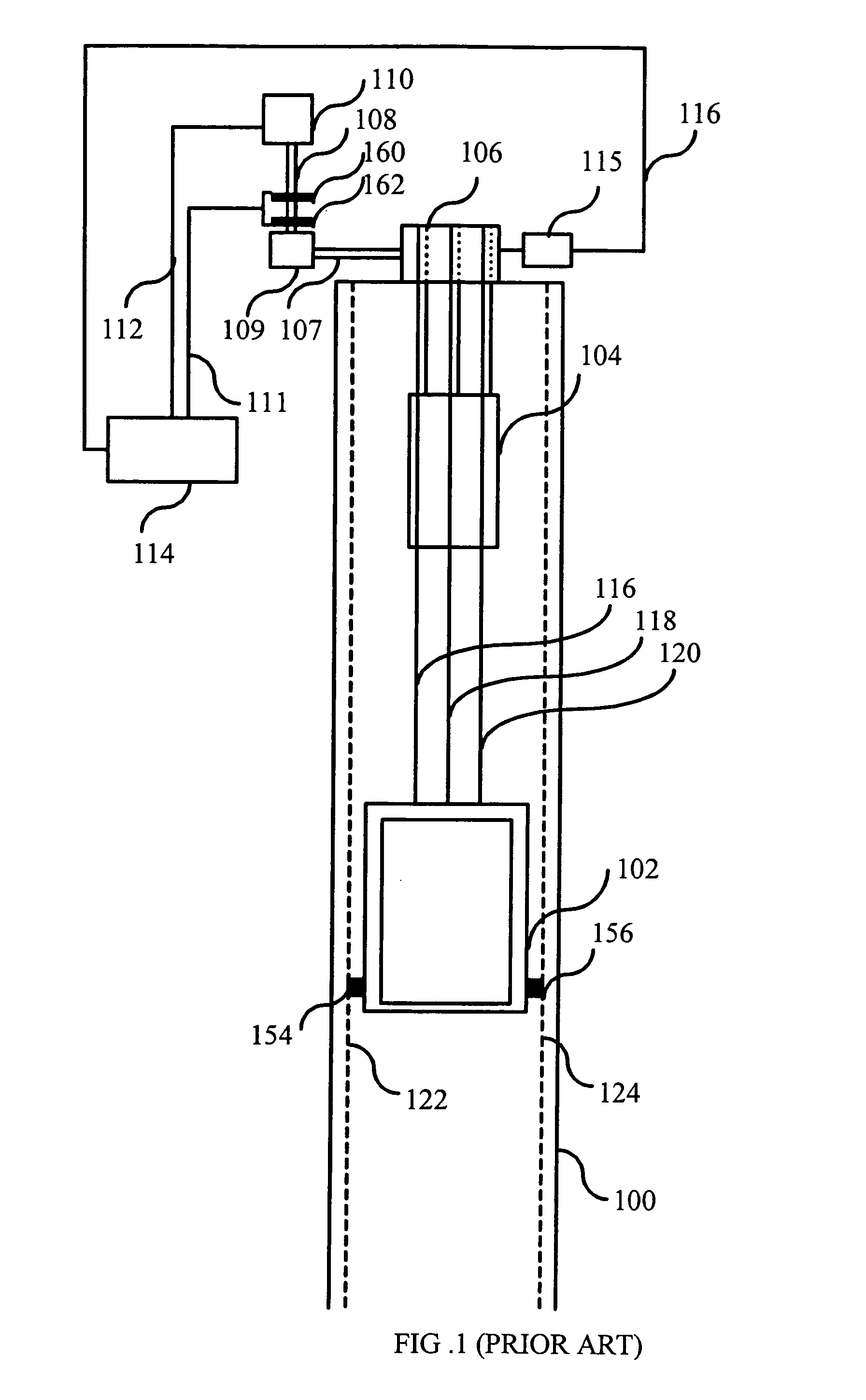
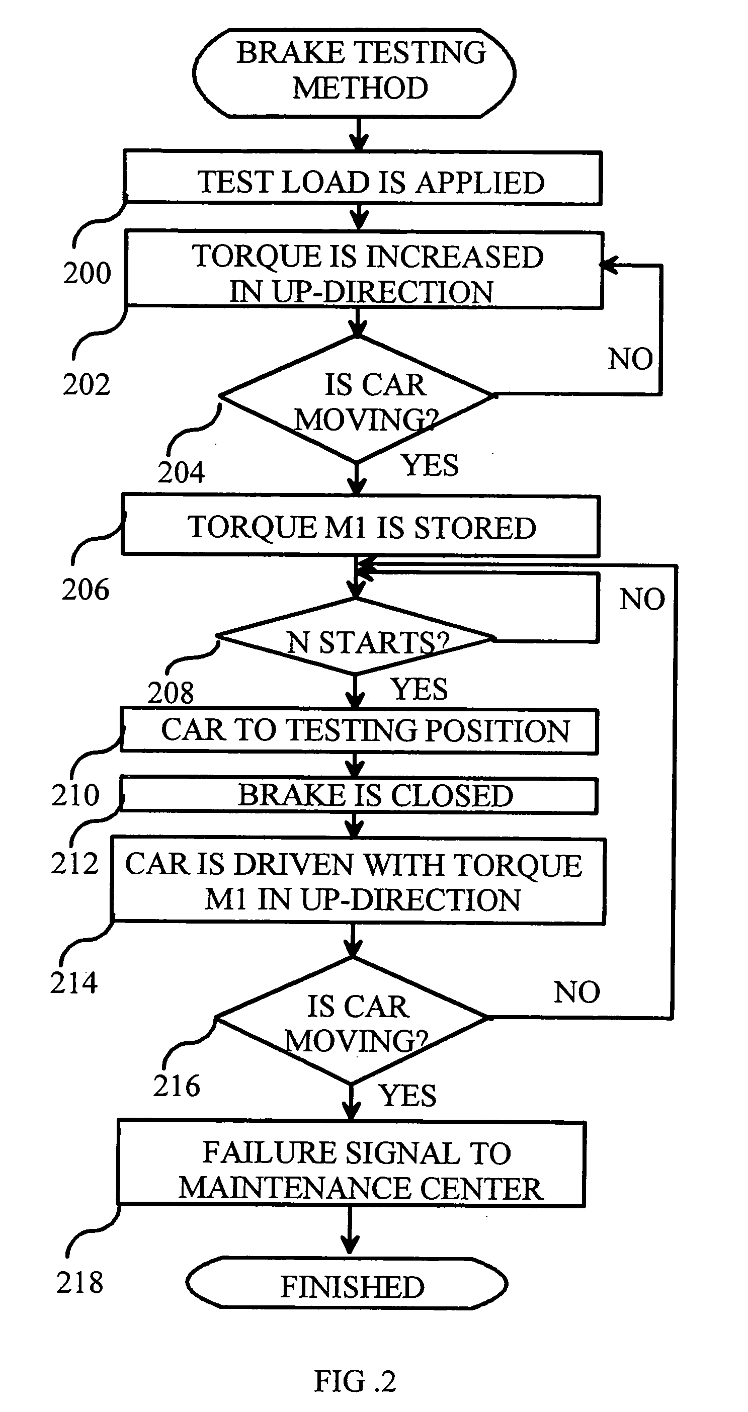
[0022]FIG. 2 presents an example of the method of the invention for testing the brakes of an elevator machine. In an embodiment of the invention, the elevator system to be tested is as illustrated in FIG. 1.

[0023]In step 200, a predefined test load is set to apply to the drive machine of the elevator. In practice, this test load is set e.g. by loading the elevator car with test weights whose weight is sufficiently reliably known. The weight of the test load depends on the amount of overload that the elevator brakes are required to tolerate. In an embodiment of the invention, the elevator brakes are required to withstand a 125-% overload. In this case, the test load must be 75 of the nominal load of the elevator. If the elevator brakes are required to withstand an overload of P %, then the test load must be 50%+P %.

[0024]In step 202, the torque of the motor 110 is increased until it is established in step 204 that the car starts moving. In step 206, the motor's 110 torque value that ...


PUM

PropertyMeasurementUnit
torqueaaaaaaaaaa
forceaaaaaaaaaa
thresholdaaaaaaaaaa

Abstract

The present invention relates to a method and a system for testing the condition of the brakes of an elevator. In the method, a test weight is set to apply to the drive machine of the elevator, by means of which weight a first torque required for driving the elevator car in the upward direction is measured. At least one of the brakes of the elevator is closed. Next, the empty elevator car is driven in the upward direction with the force of the aforesaid first torque and a check is carried out to detect movement of the elevator car. If a movement of the elevator car is detected, then the aforesaid at least one brake of the elevator is regarded as defective. The method of the present invention makes it possible to check the operativeness of the brakes of the elevator without separate maintenance visits.

Description

[0001]This application is a Continuation of copending PCT International Application No. PCT / FI2005 / 000001 filed on Jan. 3, 2005, which designated the United States, and on which priority is claimed under 35 U.S.C. § 120. The entire contents of each of the above documents is hereby incorporated by reference.FIELD OF THE INVENTION[0002]The present invention relates to elevator safety systems and the brake equipment of elevator cars.BACKGROUND OF THE INVENTION[0003]An important aim in elevator systems is to maximize passenger safety. Free fall of the elevator car must be prevented and the motion must not reach an uncontrolled acceleration and consequent uncontrolled deceleration of motion. Sudden stops occurring even with a relatively low kinetic energy may cause injuries to passengers.[0004]FIG. 1 illustrates a prior-art roped elevator system and associated common prior-art safety devices. The basic parts constituting the elevator system are an elevator shaft 100, an elevator car 102 ...

Claims


Application Information

Patent Timeline
Patent Type & Authority Patents(United States)
IPC IPC(8): B66B1/34B66B5/00G01L5/28G01M99/00
CPCB66B5/0093G01L5/288B66B5/0037
Inventor HANNINEN, ARI
Owner KONE CORP
Why Eureka
Try Eureka