Dual sprayer with external mixing chamber

a dual-tunnel sprayer and mixing chamber technology, which is applied in the direction of single-unit apparatus, lighting and heating apparatus, combustion types, etc., can solve the problems of incomplete mixing of dual-tunnel spray liquids, ineffective mixing of disparate sprays at or on the target, etc., and achieve the effect of enhancing turbulen

Active Publication Date: 2007-05-29
SILGAN DISPENSING SYST CORP
View PDF15 Cites 120 Cited by
  • Summary
  • Abstract
  • Description
  • Claims
  • Application Information

AI Technical Summary

Benefits of technology

[0004]It is therefore an object of the present invention to provide a dual sprayer having an external mixing manifold to assure intimate commingling of spray particles of separate liquids issuing through separate discharge orifices each provided with its own spin mechanics assembly. The mixing manifold may be in the form of an external attachment mounted at the downstream end of a nozzle cap containing a pair of discharge orifices for the separately issuing liquids. The manifold has a single discharge port through which the combined liquids issue as a spray, stream or foam. The manifold may define a smooth-walled mixing chamber so arranged relative to the discharge orifices that the spray particles impact against the smooth walls causing spray particles of both liquids to intimately commingle before issuing as a combined spray or stream from a discharge port of the adaptor. For foaming, an air aspiration opening may be defined by the attachment permitting ingested air to mix with the commingling separate sprays so as to issue through the discharge port of the attachment as a foam. A foaming screen may be provided at the discharge port for foaming. And, an external guide tube or ring on the attachment at its discharge port can be provided for directing the spray or foam to a selected area of a target. Swirl vanes may be provided on the inner wall of such a tube or ring to even further enhance a commingling of the two separately issuing liquids. And, the external mixing chamber may include some type of baffled geometry such as ribs, vanes, bumps, grooves, a rough surface finish, etc., to enhance turbulence in the mixing chamber to provide for a more intimate combining of the dual liquids before issuing through the attachment nozzle.

Problems solved by technology

It has been found that commingling of disparate sprays at or on the target may be ineffectual as the outer fines of each spray become airborne before they can possibly be entrained into the center.
This, therefore, results in incomplete mixing of the dual spray liquids which is undesirable and could be harmful depending on the chemical nature of the sprays combined.

Method used


Image

  • Dual sprayer with external mixing chamber
  • Dual sprayer with external mixing chamber
  • Dual sprayer with external mixing chamber

Examples


Embodiment Construction

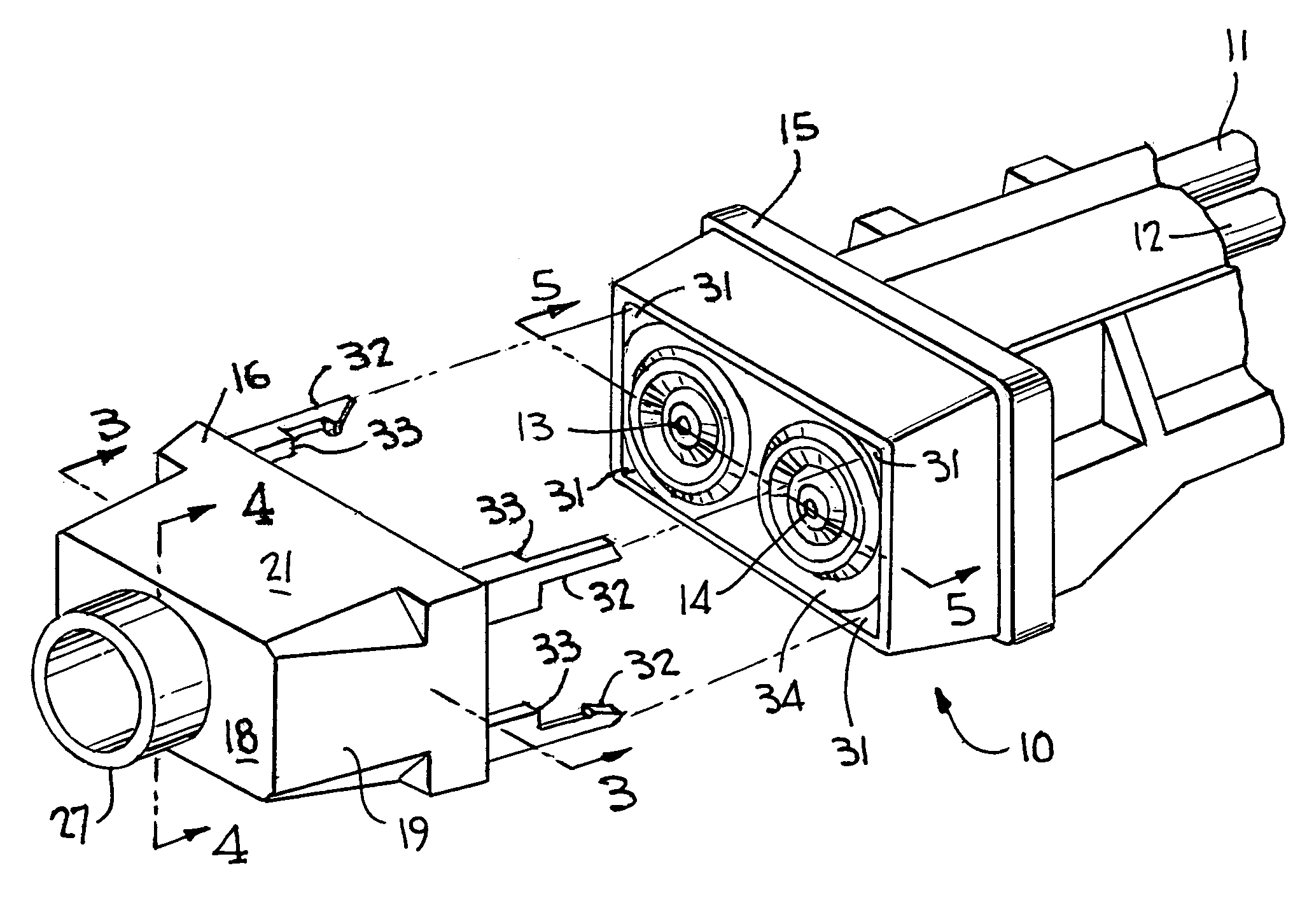
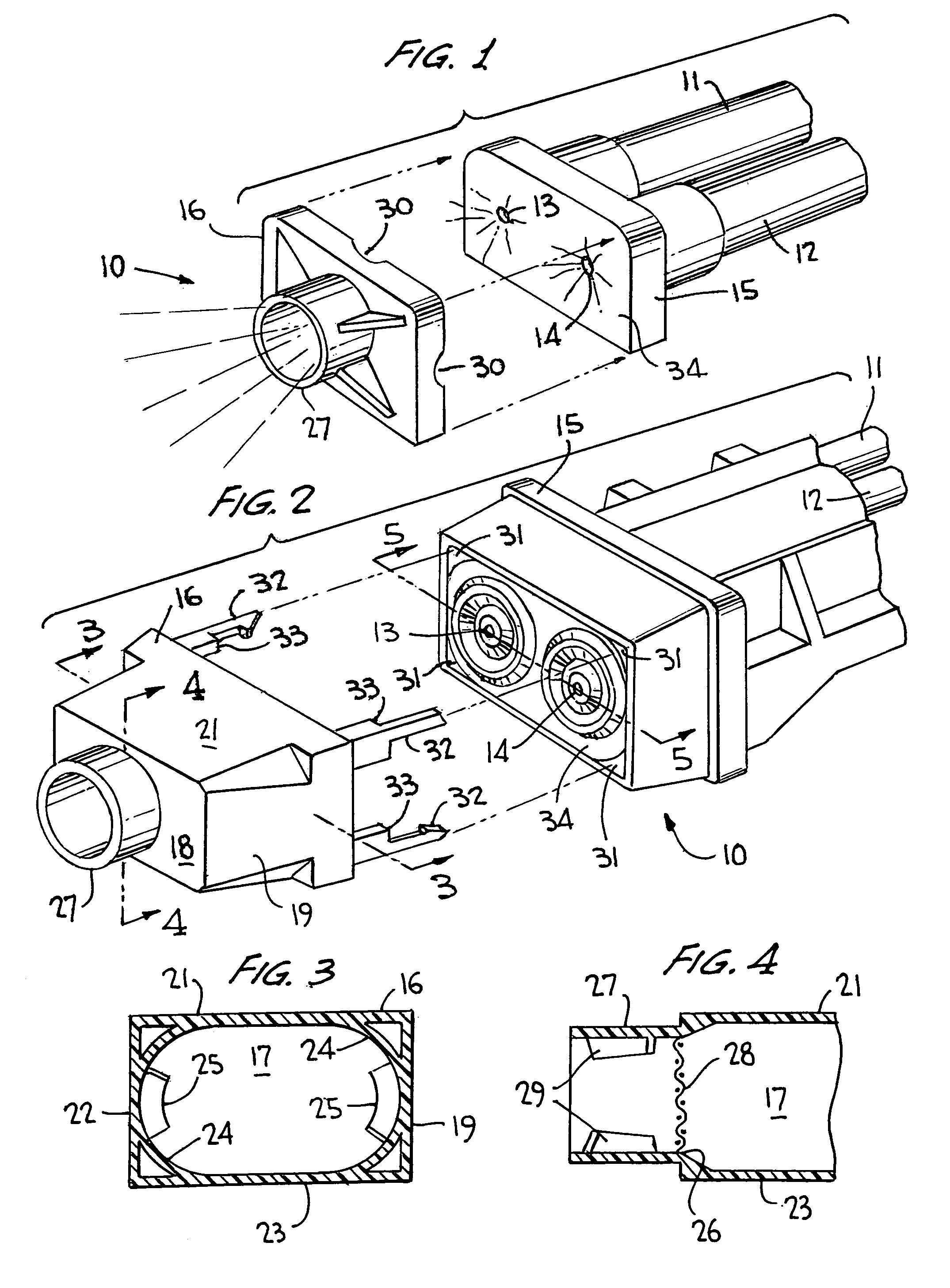
[0013]Turning now to the drawings wherein like reference characters refer to like and corresponding parts throughout the several views, the dual piston trigger sprayer according to the invention, generally designated 10 and partially shown in FIGS. 1, 2 and 6, is part of a dual sprayer as fully shown in U.S. Pat. No. 5,535,590 , commonly owned herewith, and the entirety of the disclosure of which being specifically incorporated herein by reference. Thus, the dual sprayer comprises the side-by-side pump units simultaneously actuated by a single trigger lever for suctioning first and second liquids separately stored into the pump chambers of the pumping mechanisms and discharging the separate liquids through separate side-by-side discharge barrels for issuance as separate sprays to a separate spin mechanics assemblies as shown in FIG. 10 of the U.S. Pat. No. 5,535,950 patent. The dual sprayer of the invention, prior to mixing, is essentially the same in function and operation as that ...


PUM


Abstract

A dual sprayer has an externally mounted mixing manifold for intimately commingling disparate liquids sprayed during pumping and issuing through a nozzle as a complete admixture of dual liquids.

Description

BACKGROUND OF THE INVENTION[0001]This invention relates generally to a manually operated dual trigger sprayer, and more particularly to such a sprayer having an externally mounted mixing manifold for combining separate liquids issuing from the sprayer upon sprayer actuation.[0002]Dual trigger sprayers are known having a pair of side-by-side pistons operating in side-by-side pump cylinders for simultaneously drawing liquids separately stored and discharging the liquids through separate discharge passages issuing as separate sprays from the sprayer assembly for intermingling at or on the target. Examples of such sprayers can be found in U.S. Pat. No. 5,857,591, FIG. 6, and in U.S. Pat. No. 5,535,950, FIG. 10. Otherwise, the dual liquids are combined internally of the sprayer assembly at or upstream of the sprayer nozzle for commingling in a spin chamber or the like prior to discharge as a combined spray through a single discharge orifice in the nozzle. Examples of such sprayers can be...

Claims


Application Information

Patent Timeline
Patent Type & Authority Patents(United States)
IPC IPC(8): A62C13/62B05B7/04B05B7/10B05B11/00
CPCB05B11/00B05B7/04E02D29/025E02D29/0266E02D2600/20
Inventor SWEETON, STEVE L.
Owner SILGAN DISPENSING SYST CORP
Why Eureka
Try Eureka