Multichannel plasma area igniting burner

A plasma and combustion device technology, which is applied to gas turbine devices, combustion methods, combustion ignition, etc., can solve the problems of poor working conditions in the combustion chamber, reduced combustion efficiency, and poor combustion stability, and achieve efficient and reliable flame stability and improved combustion performance. , the effect of strong flame rigidity

Active Publication Date: 2015-09-02
PEKING UNIV
View PDF10 Cites 37 Cited by
  • Summary
  • Abstract
  • Description
  • Claims
  • Application Information

AI Technical Summary

Problems solved by technology

Spark plug ignition and plasma jet both belong to plasma ignition, but the number and area of ​​ions produced are different. The energy waste of the two is relatively serious. The spark plug with small energy consumption only discharges between the high-voltage electrode and the low-voltage electrode with a small gap. If it is inserted into the air mixture, if the flow velocity is high and the pressure and temperature are low, ignition difficulties will occur, and the

Method used


Image

  • Multichannel plasma area igniting burner
  • Multichannel plasma area igniting burner

Examples


Embodiment 1

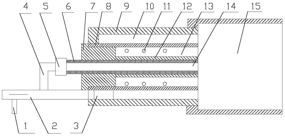
[0038] Such as figure 1 As shown, a multi-channel plasma area ignition and combustion device mainly includes a nozzle 1, an intake fish mouth 2, a tangential air hole 3, a gas pipe 4, a hollow insulator 5, a high-voltage electrode 6, an insulator 7, a low-voltage electrode 8, and a shell 9. Swirl chamber 10, air hole 11, barrier medium 12, low velocity zone 13, center jet 14, flame stabilization chamber 15; said nozzle 1 refers to a direct-flow nozzle or other nozzles, which are installed in the pipe wall of the intake fish mouth for a certain period of time. position; the air intake mouth 2 refers to the air intake pipe with splash plate atomization in the middle, which is installed on the inlet end of the shell 9 and the low-voltage electrode 8, and is sealed with the inlet; the tangential air hole 3 refers to Intake fish mouth 2 air outlet holes, the outlet hole of intake fish mouth 2 is provided with one or more blades, the outlet blades make the air flow rotate at high sp...

Embodiment 2

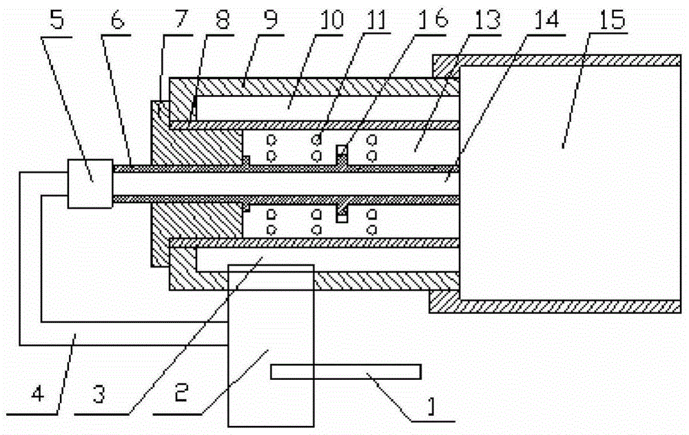
[0040] Such as figure 2 As shown, a multi-channel plasma area ignition and combustion device mainly includes a nozzle 1, an intake fish mouth 2, a tangential air hole 3, a gas pipe 4, a hollow insulator 5, a high-voltage electrode 6, an insulator 7, a low-voltage electrode 8, and a shell 9. Swirl chamber 10, air holes 11, protrusions 16, low-velocity zone 13, center jet 14, flame stabilization chamber 15; the nozzle 1 refers to a direct-flow nozzle or other nozzles, which are installed in the wall of the intake fish mouth A certain position; the air intake mouth 2 refers to the air intake pipe with a splash plate atomization in the middle, which is installed at the upstream of the shell and is sealed with the shell; the tangential air hole 3 refers to a rectangular air intake , whose height is the same as the radial distance of the swirl chamber, which is arranged at the upstream of the shell to ensure that the high-speed airflow enters the swirl chamber to generate a high-sp...


PUM


Abstract

The invention discloses a multichannel plasma area igniting burner. The igniting burner comprises a plasma power supply, a nozzle, an air inlet fish nozzle, a tangential air hole, an air pipe, a hollow insulator, a high-voltage electrode, an insulation piece, a low-voltage electrode, a housing, a swirl chamber, air vents, barrier mediums, a low-speed area, center jet flow and a flame stabilization chamber. Fuel oil is atomized by the use of a splash plate disposed inside the air inlet pipe, mixed gas composed of high-speed rotation air-flow and direct current jet flow is disposed inside the igniting burner, and the two flows cool the igniting burner. The space between the high-voltage electrode and the low-voltage electrode is filled with the inflammable mixed gas flowing at a low speed, so that multi-point discharge and ignition can be carried out in a low-speed mixed gas area inside the igniting burner; and an on-duty high-temperature combustion thermonuclear area and the flame stabilization chamber have ignition source and flame stabilization functions and form a miniature high-speed combustion chamber, so that the combustion chamber can efficiently and reliably ignite and keep flames stable under poor conditions such as high-speed, low-temperature, low-pressure, coal firing and the like.

Description

technical field [0001] The invention relates to the field of aerospace technology and the field of industrial combustion, in particular to a multi-channel plasma region ignition and combustion device. Background technique [0002] Common ignition methods include hot surface, laser-induced spark, spark plug and plasma flow. They all heat the unburned gas mixture to increase its temperature, generate initial free radicals, and then initiate a chain reaction from these initial free radicals. For hot surface ignition, the ignition delay time is longer and the life is relatively short; laser-induced spark ignition requires focused high-energy laser pulses; spark plug ignition is a widely used and relatively reliable ignition method. The above-mentioned ignition methods all have the problem of small ignition area. When the combustion conditions are very bad, such as high-altitude low-pressure ignition, supersonic combustion, lean combustion, etc., the applicability and reliability...

Claims


Application Information

Patent Timeline
IPC IPC(8): F23Q13/00F02C7/266
Inventor 郑殿峰张会强林文漪
Owner PEKING UNIV
Why Eureka
Try Eureka