Heat exchanger of ventilating system

a technology of heat exchanger and ventilating system, which is applied in the field of ventilating system, can solve the problems of degrading heat exchange efficiency, increasing energy consumption for recovering indoor air, and rapid change of indoor temperature, so as to improve heat exchange performance and increase the turbulence of air passing

Inactive Publication Date: 2007-06-12
LG ELECTRONICS INC
View PDF15 Cites 46 Cited by
  • Summary
  • Abstract
  • Description
  • Claims
  • Application Information

AI Technical Summary

Benefits of technology

[0019]Therefore, an object of the present invention is to provide a heat exchanger of a ventilating system, capable of improving heat transfer performance by increasing turbulence of air passing through an air path by positioning a mesh type air path through which outdoor and indoor air passes.
[0020]To achieve these and other advantages and in accordance with the purpose of the present invention, as embodied and broadly described herein, there is provided a heat exchanger of a ventilating system, including a plurality of heat exchanging plates which are laminated at a predetermined interval, a first heat exchange member which is laminated among the heat exchanging plates and is formed in a mesh type to increase turbulence of the outdoor air which flows while being attached on a first air path through which outdoor air passes and a second heat exchange member which is laminated among the heat exchanging plates while being crossed with the first heat exchange member and is formed in a mesh type to increase turbulence of indoor air which flows while being attached on a second air path through which the indoor air passes.

Problems solved by technology

Therefore, heat transfer efficiency is degraded and indoor temperature is rapidly changed in case of ventilating since the outdoor air sucked to the indoor could not absorb heat in the indoor air.
Also, energy consumption for recovering the indoor air is increased and indoor air conditioning performance is degraded.

Method used


Image

  • Heat exchanger of ventilating system
  • Heat exchanger of ventilating system
  • Heat exchanger of ventilating system

Examples


Embodiment Construction

[0036]Reference will now be made in detail to the preferred embodiments of the present invention, examples of which are illustrated in the accompanying drawings.

[0037]As the embodiment of the heat exchanger of the ventilating system in accordance with the present invention, there can be a plurality of them, and hereinafter, the most preferable one will be described.

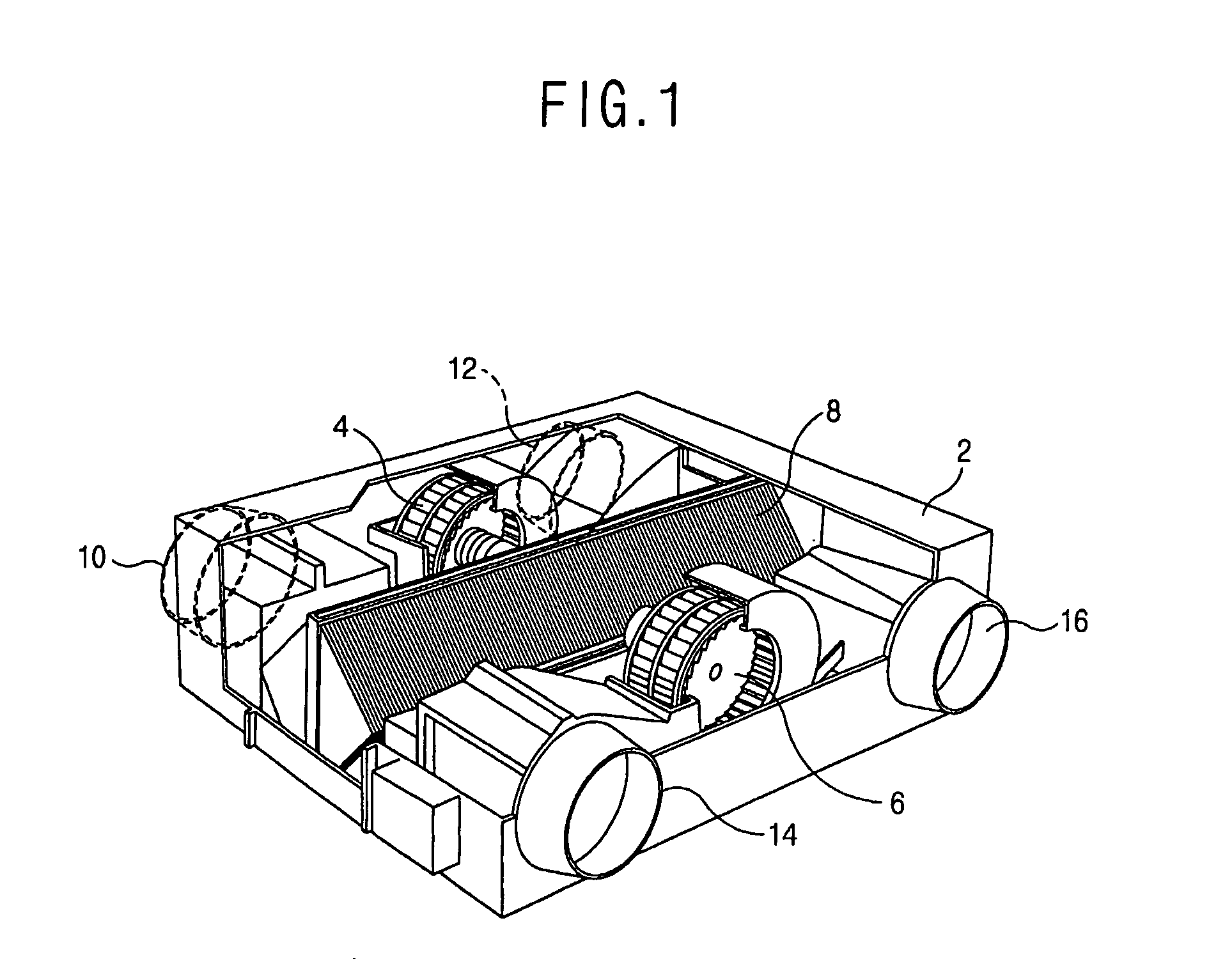
[0038]FIG. 5 is a perspective view showing a heat exchanger of a ventilating system in accordance with the present invention.

[0039]With reference to FIG. 1, in the ventilating system in accordance with the present invention, a case 2 is mounted to penetrate a wall which divides the indoor and outdoor, a side surface of the case 2 is positioned outdoors and the other side surface is positioned indoors. Here, an outdoor suction hole 10 through which the outdoor air is sucked and an outdoor discharging hole 12 through which the indoor air is discharged are respectively formed on a side surface positioned at the outdoor of th...


PUM


Abstract

A heat exchanger of a ventilating system, including a plurality of heat exchanging plates which are laminated at a predetermined interval, a first heat exchange member which is laminated among the heat exchanging plates and is formed in a mesh type to increase turbulence of the outdoor air which flows while being attached on a first air path through which outdoor air passes and a second heat exchange member which is laminated among the heat exchanging plates crossed with the first heat exchange member and is formed in a mesh type to increase turbulence of indoor air which flows while being attached on a second air path through which the outdoor air passes can improve heat transfer performance by increasing turbulence of air by positioning a mesh type heat exchange in a air path through which outdoor and indoor air passes.

Description

TECHNICAL FIELD[0001]The present invention relates to a ventilating system for exchanging indoor air and outdoor air and particularly, to a heat exchanger of a ventilating system, capable of improving heat exchanging performance between outdoor air and indoor air.BACKGROUND ART[0002]Generally, a ventilating system is a system for discharging polluted indoor air to the outdoor and sucking fresh outdoor air to the indoor, and the system includes an air cleaner for removing dust and foreign materials contained in the outdoor air, and a heat exchanger for transferring heat of the discharged indoor air to the sucked outdoor air.[0003]FIG. 1 is a perspective view showing a conventional ventilating system.[0004]The ventilating system includes a case 2 which is mounted on a wall for dividing indoor and outdoor, blowing fans 4 and 6 which are mounted in the case 2, for ventilating air which is sucked and discharged, an air cleaner (not shown) which is installed in a portion to which the outd...

Claims


Application Information

Patent Timeline
Patent Type & Authority Patents(United States)
IPC IPC(8): F28F3/02F24F12/00F28D9/00F28F13/12
CPCF24F12/006F28F13/12F28D9/0062Y02B30/563Y02B30/56
Inventor SHIN, SOO-YEONLEE, SEONG-HWANCHO, MIN-CHULLEE, SUNG-HWA
Owner LG ELECTRONICS INC
Why Eureka
Try Eureka