Drip irrigation hoses of the labyrinth type and flow-control elements for producing such hoses

a technology of labyrinth and hose, which is applied in the direction of spray nozzles, climate change adaptation, horticulture, etc., can solve the problems of clogging, difficulty in removing clogging particles, and difficulty in ensuring relatively uniform discharge rates along the length of the hose, so as to reduce the thickness, the effect of increasing the height and slowing down the ra

Inactive Publication Date: 2008-03-20
COHEN
View PDF11 Cites 44 Cited by
  • Summary
  • Abstract
  • Description
  • Claims
  • Application Information

AI Technical Summary

Benefits of technology

[0014]According to another aspect of the present invention, there is provided a drip irrigation hose, comprising a tube for conducting pressurized water through its interior, and formed with a plurality of tube outlets for discharging the water at longitudinally-spaced locations along the length of the tube; and a plurality of flow-control elements secured to the inner surface of said tube at longitudinally-spaced locations thereof to define, with said inner surface, a plurality of labyrinths, each having an inlet at one end communicating with the interior of the tube and an outlet at the opposite end communicating with a tube outlet for discharging water there from at a slow rate; the inlet of each labyrinth being defined by a plurality of spaced projections engageable with the inner surface of the tube to form a plurality of filtering inlet passageways for the water entering the respective labyrinth from the interior of the tube; the plurality of spaced projections being arrayed in an outer line and in an inner line in a staggered relationship with respect to those of the outer line; the projections of the outer line being of larger height and of decreasing thickness with increasing height. This feature is advantageous in reducing the possibility

Problems solved by technology

One problem in using drip irrigation hoses is the difficulty in ensuring relatively uniform discharge rates along the length of the hose.
This problem is particularly acute where extremely long lengths of the hose are used since the hose itself produces a pressure drop along its length tending to decrease the discharge rate at the end of the hose.
This sensitivity of discharge rate to the water pressure is als

Method used


Image

  • Drip irrigation hoses of the labyrinth type and flow-control elements for producing such hoses
  • Drip irrigation hoses of the labyrinth type and flow-control elements for producing such hoses
  • Drip irrigation hoses of the labyrinth type and flow-control elements for producing such hoses

Examples


Embodiment Construction

The Overall Construction

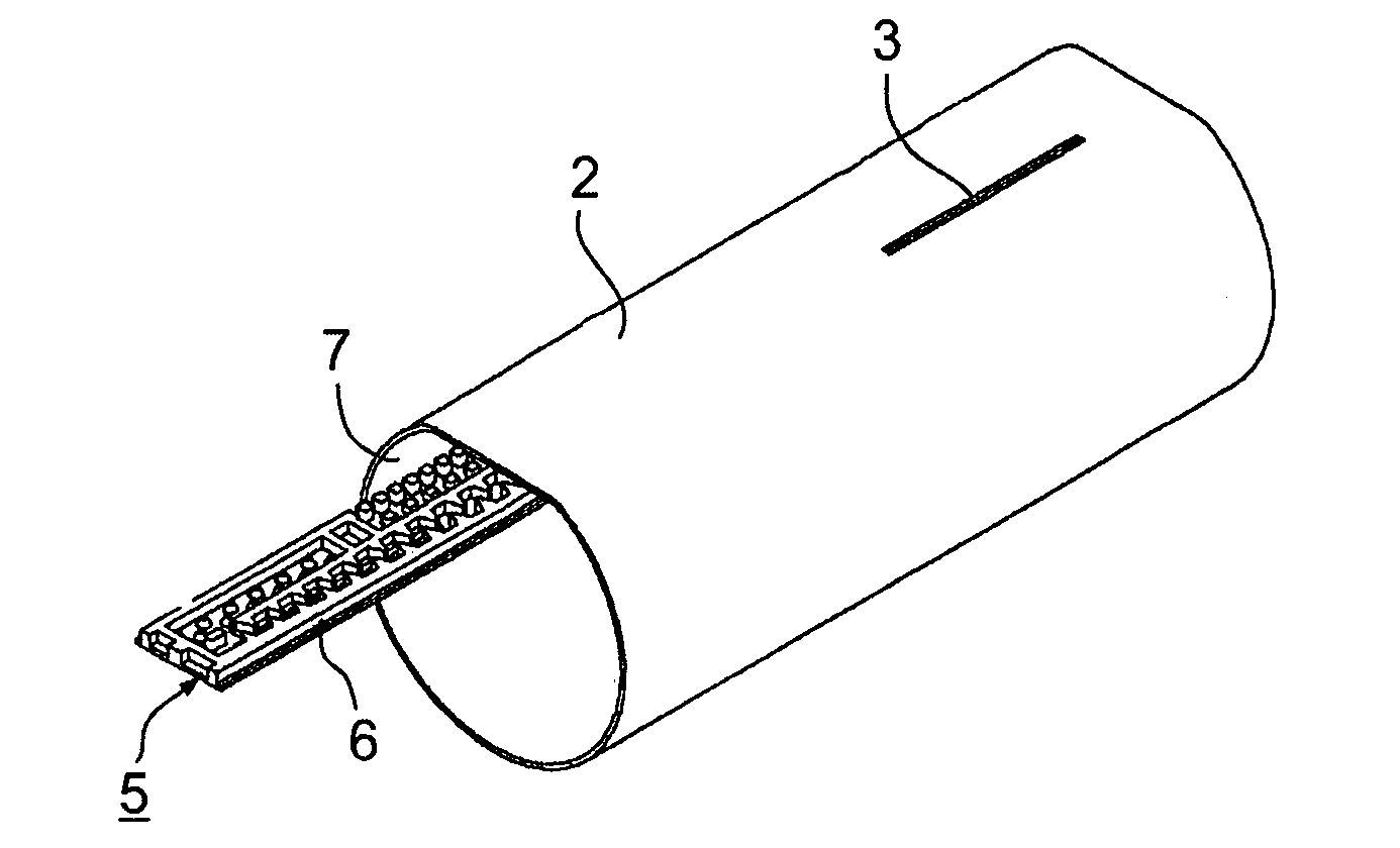
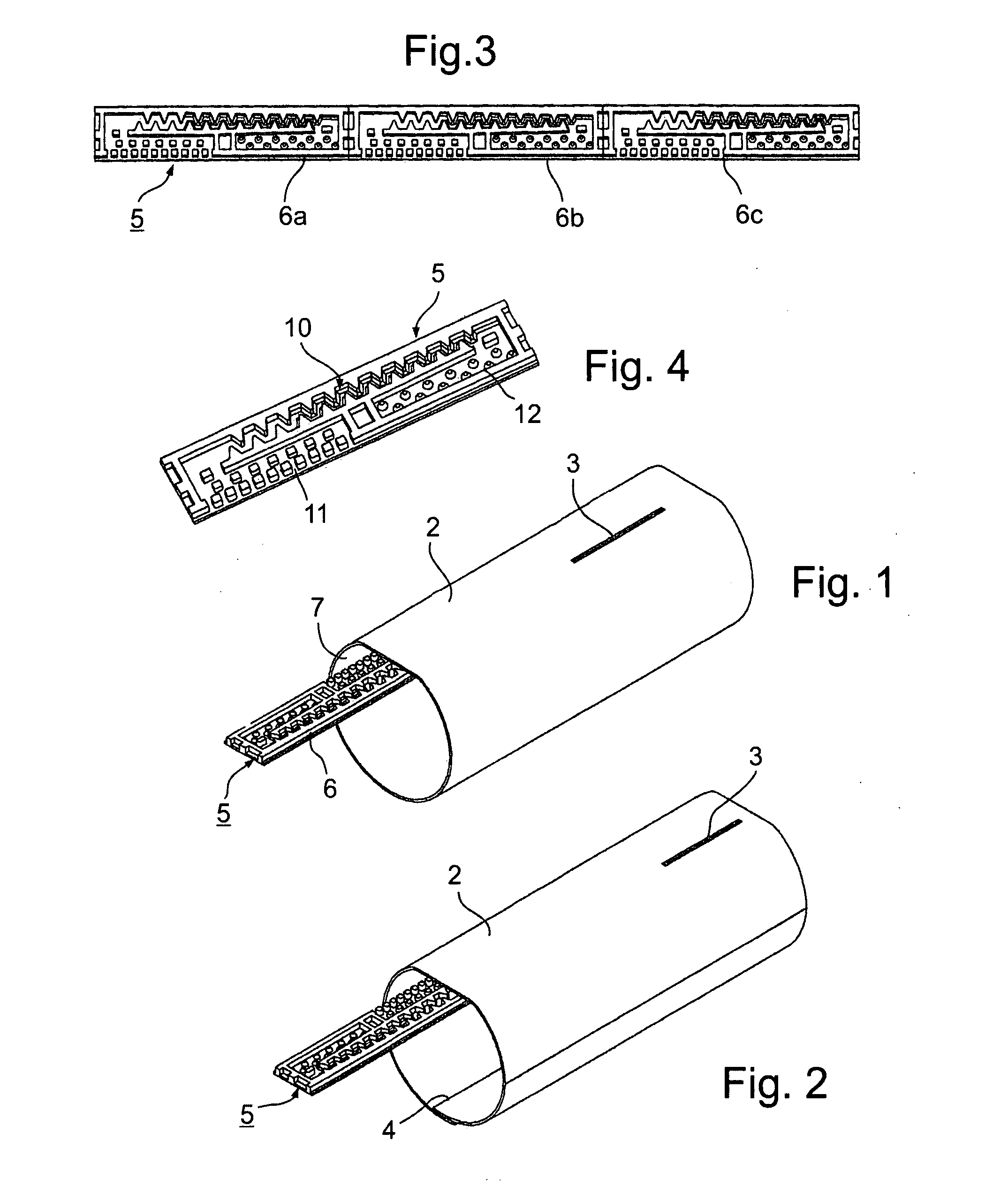
[0046]As shown in FIGS. 1 and 2, the illustrated drip irrigation hose comprises a tube 2 for conducting pressurized water through its interior and formed with a plurality of tube outlets 3 (only one of which is shown) for discharging water at a slow rate at longitudinally-spaced locations along the length of the tube. FIG. 1 illustrates a seamless-type (extruded) tube; whereas FIG. 2 illustrates a seamed-type tube, including a seam 4.

[0047]The illustrated drip irrigation hose further comprises a continuous strip 5 formed with a plurality of flow-control elements 6a-6c be fixed with respect to the inner surface 7 of tube 2 at longitudinally-spaced locations thereof to define, with the inner surface of the tube, a plurality of labyrinths 10. Each labyrinth 10 has an inlet 11 at one end communicating with the interior of the tube, and an outlet 12 at the opposite end communicating with a tube outlet 3 for discharging water there from at a slow rate. FIG. 4 illus...


PUM


Abstract

A drip irrigation hose includes a tube for conducting pressurized water through its interior and formed with a plurality of outlets for emitting water at longitudinally-spaced locations along the length of the tube; and a plurality of flow-control elements fixed with respect to the inner surface of the tube at longitudinally-spaced locations thereof to define, with the inner surface, a plurality of labyrinths each having an inlet communicating with the interior of the tube and an outlet communicating with a tube outlet for emitting water there from at a slow rate. The labyrinth includes a bottom wall constructed to produce, adjacent to the bottom wall, a significant laminar flow of water in which the laminar flow decreases, and thereby turbulent flow increases, with an increase in the water pressure within the tube to thereby provide pressure-compensation for the water flow through the respective tube outlet.

Description

FIELD AND BACKGROUND OF THE INVENTION[0001]The present invention relates to drip irrigation devices, and particularly to drip irrigation hoses used for discharging the irrigation water at slow rates from a plurality of longitudinally-spaced locations along the length of the hose. The invention also relates to flow-control elements for producing such hoses.[0002]Drip irrigation hoses are increasingly being used for irrigating various types of plants since, among other advantages; they supply the water directly to the root regions of the plants and are therefore highly conservative of water and fertilizer. One type of drip irrigation hose includes a tube for conducting pressurized water through its interior and formed with a plurality of tube outlets for discharging the water at longitudinally-spaced locations along its length, and a plurality of flow-control elements fixed with respect to the inner surface of the tube to define a plurality of labyrinths, each having an inlet at one e...

Claims


Application Information

Patent Timeline
IPC IPC(8): B05B15/00
CPCA01G25/023Y02A40/22
Inventor COHEN, AMIR
Owner COHEN
Why Eureka
Try Eureka