Multiple swivel flashlight

a flashlight and swivel technology, applied in portable electric lighting, light and heating apparatus, electric batteries, etc., can solve the problems of difficult temporary setup in a free-standing position, limited single lamp and reflector of lantern or single in-line conventional flashlight, etc., to achieve maximum user selectability and preserve battery power

Inactive Publication Date: 2007-05-29
DAKA RESEARCH INC
View PDF6 Cites 41 Cited by
  • Summary
  • Abstract
  • Description
  • Claims
  • Application Information

AI Technical Summary

Benefits of technology

[0007]The support arms support the reflectors at an angle in order to enable the user to optimally adjust the position of the multiple swivel flashlight, so that the reflectors can be positioned to not interfere with each other. With the light reflectors positioned to pivot from lines placed at an angle to the base, the base may be carried in the same manner as a conventional flashlight with both light beams being directed forward, with the beams either focussed at an area or divergingly spread apart. In the alternative, the top reflector can be directed upwardly to provide light reflected from a ceiling while the bottom reflector can be directed forward to enable directed placement of the beam. In the alternative, and particularly when no ceiling is present, the bottom reflector can be directed downwardly to illuminate the path for better walking while the top reflector is directed forward to illuminate areas much farther forward of the user.
[0009]A telescoping embodiment is disclosed which shows three reflectors and enables both pivoting and height and reflector spacing by the provision of a telescoping version of the reflector supports. The current supplied to the reflectors is provided through insulated telescoping supports which have a system of internal conductance surfaces with current transferred by a wiping structure regardless of the height of deployment of the telescoping structure. A swich may be provided for selective energization of one or more of the reflectors independently in order to conserve battery power and to provide for maximum user selectability.

Problems solved by technology

As a prime example, utility lights have a large six-volt lantern size battery and are handy and balanced for carrying, but awkward for setting up for use in a free-standing application.
Cylindrical in line battery type hand held flashlights have the same problem, they are difficult to temporarily set up in a free-standing position.
Further, either the lantern or single in line conventional flashlight have the limitation of a single lamp and reflector.
However these systems are not portable nor carryable into tight working spaces where both the ability to aim and direct the light may be compromised, as well as the ability to apply more than one source of light.
Failure mode is another area where conventional portable lighting typically fails.
In a close dark work space, the failure of the main bulb element can leave a worker totally in the dark, unless he carries a backup light source.
Even when a backup source is carried, it may be difficult to locate where the worker is plunged into darkness unexpectedly.

Method used


Image

  • Multiple swivel flashlight
  • Multiple swivel flashlight
  • Multiple swivel flashlight

Examples


Embodiment Construction

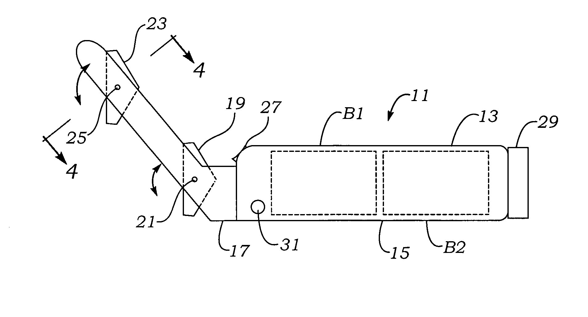
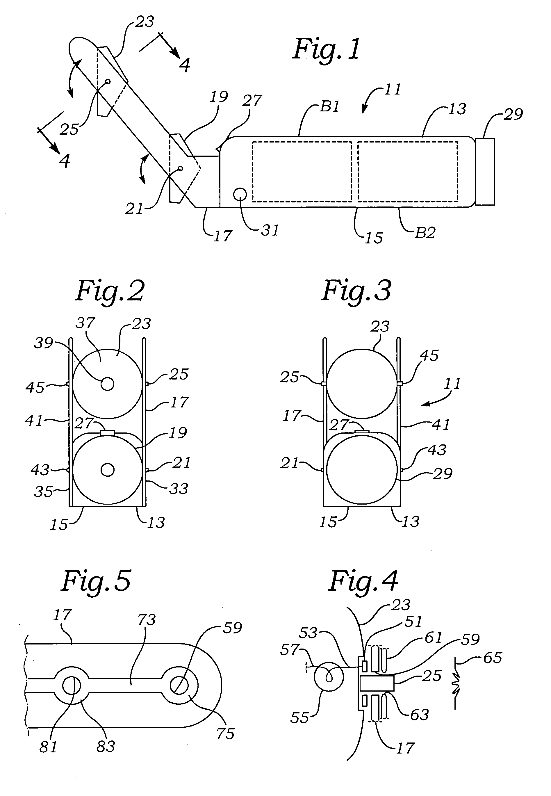
[0021]A multiple swivel flashlight 11 includes a main housing 13, preferably having a flat base 15 for improved stability when placed on a nearly horizontal surface. The multiple swivel flashlight 11 is shown is a two reflector embodiment. From the side view of FIG. 1, a first conducting reflector support arm 17 can be seen as supporting a

[0022]first axially pivotable reflector 19 at a pivot point seen as a first reflector first pivot axis fitting 21. First conducting reflector support arm 17 can also be seen as supporting a second axially pivotable reflector 23 at its pivot point seen as a second reflector first pivot axis fitting 25.

[0023]A positive electrical and mechanical engagement rocker switch 27 can be partially seen as placed in a position on the main housing 13 to enable thumb manipulation but with a positive on and off operation as is advantageous for both carried and placed utilization of the multiple swivel flashlight 11. At the end of multiple swivel flashlight 11 a b...


PUM


Abstract

A multiple swivel flashlight provides a stable housing with flat bottom for ready support on most surfaces, as well as a pair of lamp reflector arms which are either conducting or carry conductors to supply the reflectors with the voltage and current needed to drive the lamps. Where the exterior of the support arms are conducting, they are either coated or painted to insulate the exterior. Where the support arms are non-conducting, conductors are either inlaid or attached, preferably along the interior surface of the conductors. The support arms support the reflectors at an angle in order to enable the user to optimally adjust the position of the multiple swivel flashlight.

Description

FIELD OF THE INVENTION[0001]The present invention relates to lighting equipment and more particularly to flashlight having double swiveling illumination elements which can be independently angularly adjusted. The angular relationship of the illumination elements enables the user to either carry or set the flashlight down for advantageous usage.BACKGROUND OF THE INVENTION[0002]A number of systems have been available for illumination. The constant which has heretofore been present in portable illumination is the design conflict between a carried or portable lighting unit and a stable or independently supported unit. As a prime example, utility lights have a large six-volt lantern size battery and are handy and balanced for carrying, but awkward for setting up for use in a free-standing application. Cylindrical in line battery type hand held flashlights have the same problem, they are difficult to temporarily set up in a free-standing position.[0003]Further, either the lantern or singl...

Claims


Application Information

Patent Timeline
Patent Type & Authority Patents(United States)
IPC IPC(8): F21L4/02
CPCF21L4/04F21V17/02F21V21/145F21V21/22
Inventor MAH, PAT Y.
Owner DAKA RESEARCH INC
Why Eureka
Try Eureka