
Double-acting, high pressure cryogenic pump

a cryogenic pump and double-acting technology, applied in the direction of positive displacement liquid engines, container discharging methods, liquid fuel engines, etc., can solve the problems of significant accumulation of fluid vapors from blow-by leakage in high-pressure cryogenic pumps, and none of these patents teach or suggest an effective method for blow-by leakage venting, etc., to achieve less liquid, less cool down time, and small physical size

Active Publication Date: 2007-05-29
DURON PAUL DAVID MR
View PDF8 Cites 13 Cited by
  • Summary
  • Abstract
  • Description
  • Claims
  • Application Information

AI Technical Summary

Benefits of technology

[0017]Also a double-acting pump having the same capacity as a single-acting pump is significantly smaller in physical size. This feature is very important for cryogenic fluid pumps because less liquid and less cool down time are required for system cool down, i.e., preparation for system startup. The nearly continuous flows to and from the double-acting pump allows a reduction in diameter of the suction and discharge piping. This factor may reduce heat leak into the cryogenic liquid. The smoother and reduced maximum rate of inflow to the double-acting pump reduces suction pipe fluid pressure drop due to decreased acceleration of the cryogenic fluid. Hence, decreased net positive suction pressure required for pump operation. The improved suction performance can eliminate the requirement for a boost pump and associated piping.
[0019]Another advantage is that increased capacity can be obtained by using multi-cylinder, double-acting, reciprocating piston, cryogenic fluid pumps. By this it is meant that multiple, double-acting, reciprocating piston, cryogenic fluid pumps can be operated in parallel to increase capacity.

Problems solved by technology

The generation and accumulation of fluid vapors from blow-by leakage in high pressure cryogenic pumps is a significant problem unless the vapors are collected and condensed in cold low pressure liquid.
The problem of venting “blow-by vapors” is not present in a low pressure pump.
None of these patents teach or suggest an effective method for venting of blow-by vapors in double-acting pump.

Method used


Image

  • Double-acting, high pressure cryogenic pump
  • Double-acting, high pressure cryogenic pump
  • Double-acting, high pressure cryogenic pump

Examples


Embodiment Construction

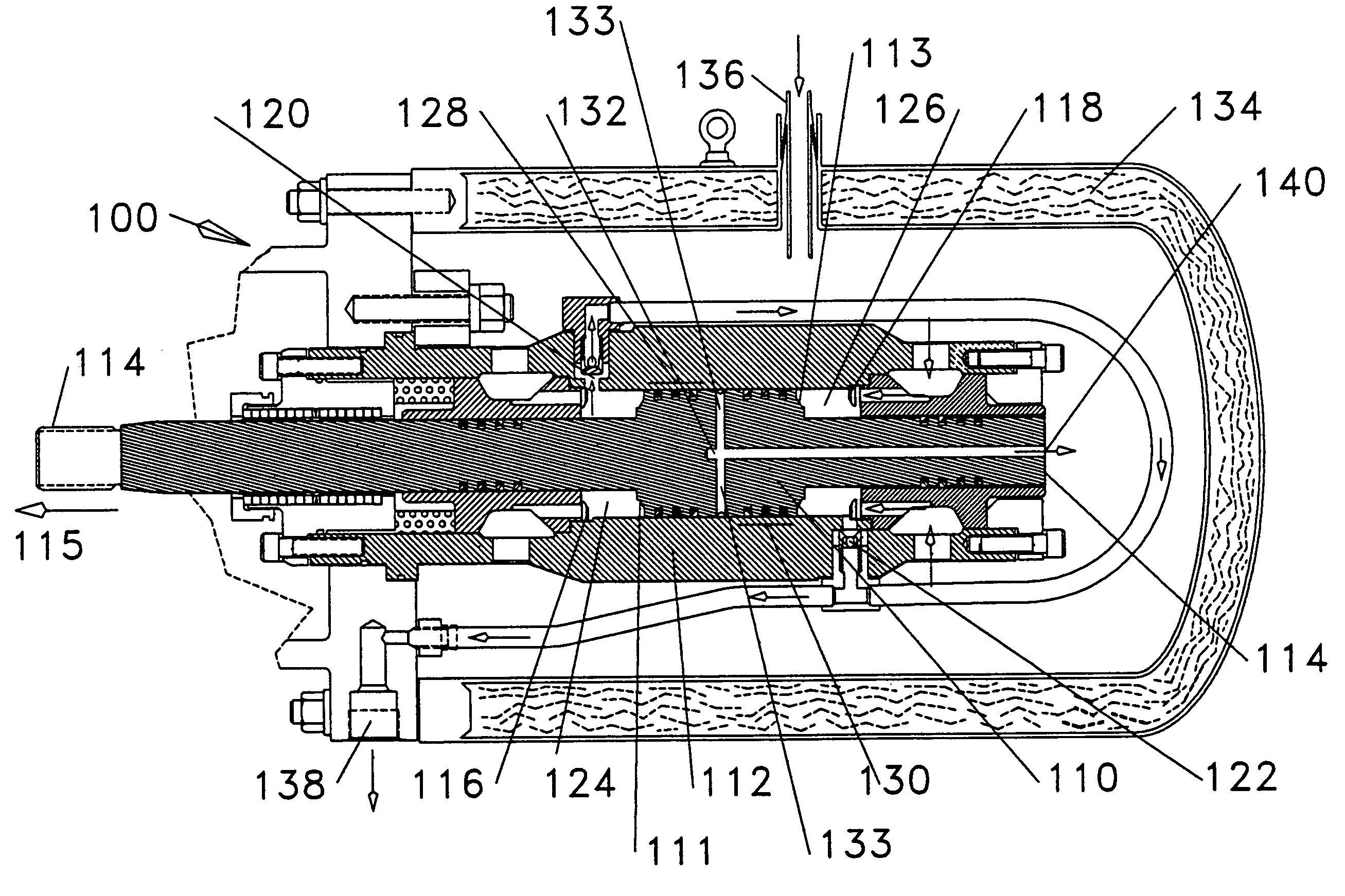
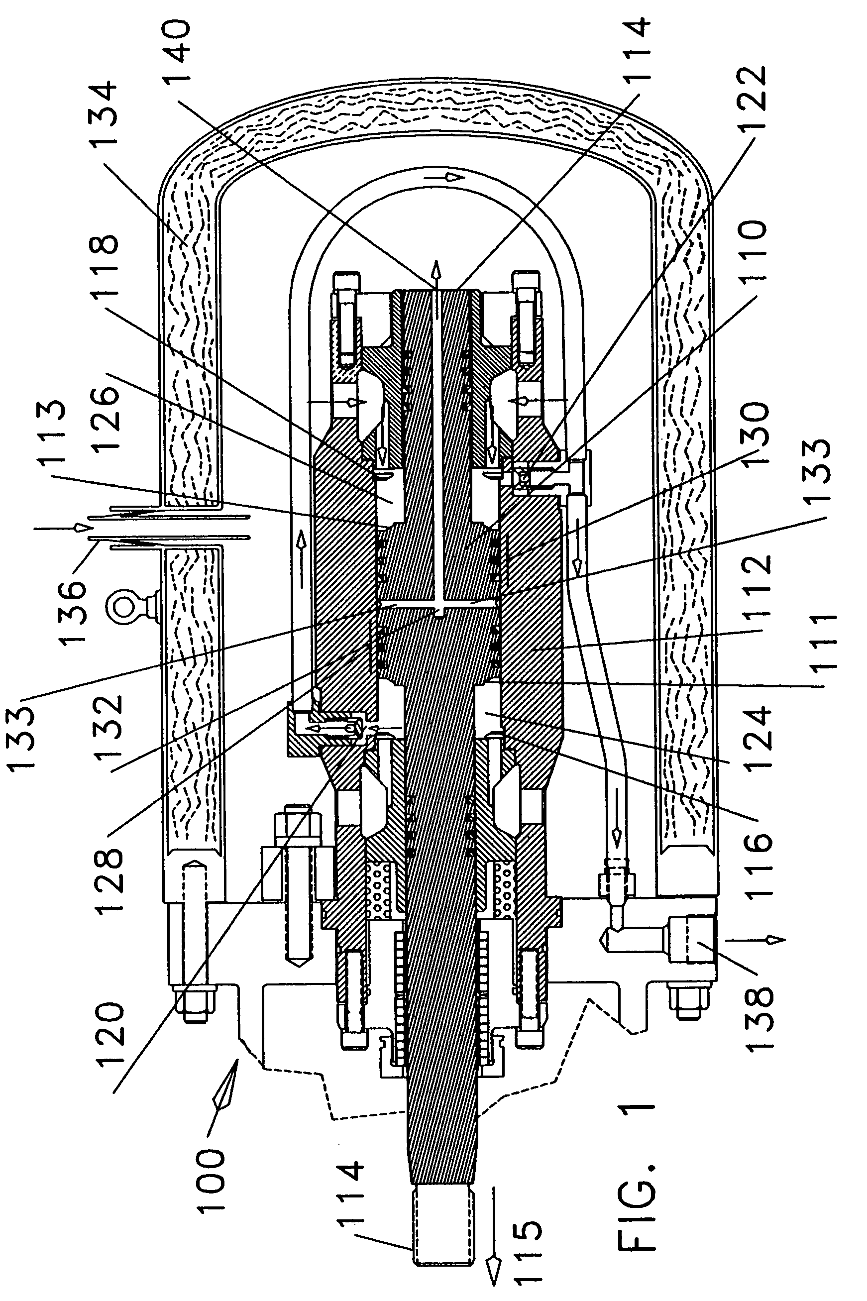
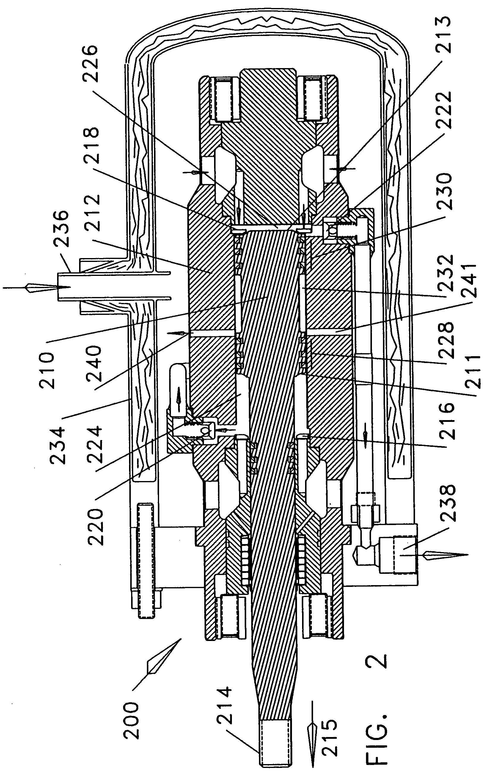
[0025]There are two embodiments of the double-acting, high pressure, cryogenic pump disclosed. In one embodiment, blow-by is vented through the piston rod while in the second embodiment, blow-by is vented through the pump cylinder housing.

[0026]Referring to FIG. 1, a cross sectional view of a double-acting, high pressure, cryogenic pump cold end 100 is illustrated. Double-acting piston 110 reciprocates in cylinder 112. The drive system or mechanism that causes piston 110 to reciprocate (not shown) is connected to piston rod 114 as is well known in the art. This mechanism normally consist of a crankshaft, a connecting rod, and a crosshead with pin. Double-acting piston 110 is shown at about mid-stroke and moving toward the left as indicated by arrow 115 at the end of piston rod 114.

[0027]Double-acting, high pressure, cryogenic pump 100 has a left side pump chamber 124 and a right side pump chamber 126. Left side pump chamber 124 as illustrated is at discharge pressure and cryogenic f...


PUM


Abstract

A double-acting, reciprocating piston, high discharge pressure, cryogenic fluid pump having a unique blow-by venting system. In two different embodiments, a double-acting piston has two pair of piston heads and two sets of seals. In a first embodiment, a blow-by vent system is provided by a passageway that communicate with the cylinder between the pair of piston heads and vents the vapor or fluids axially through the piston rod. A second embodiment has the two piston heads separated on the piston rod a distance equal approximately to the stroke of the piston. This provides an annulus around the piston rod forming a manifold in communication with passageways through the pump cylinder wall to vent blow-by vapors or fluids. In both cases, blow-by vapors or fluids that leak or creep past the piston heads are vented to the liquid being pumped inside an insulating enclosure surrounding the pumps.

Description

BACKGROUND OF THE INVENTION[0001]1. Field of the Invention[0002]This invention relates to high pressure cryogenic pumps and more particularly relates to a double-acting, reciprocating piston, high pressure (about 2,000 psi and greater) cryogenic fluid pump that provides venting of blow-by vapors between two sets of high pressure seals on a double-acting piston.[0003]2. Background Information[0004]The generation and accumulation of fluid vapors from blow-by leakage in high pressure cryogenic pumps is a significant problem unless the vapors are collected and condensed in cold low pressure liquid. This invention is directed to a method and apparatus for collecting, mixing, and condensing blow-by leakage vapors with cold suction liquid.[0005]One type of double-acting, reciprocating, piston cryogenic fluid pumps is disclosed and described in U.S. Pat. No. 5,411,374 of A. Gram issued May 2, 1995. This patent describes a double-acting, reciprocating piston, cryogenic fluid pump mechanicall...

Claims


Application Information

Patent Timeline
Patent Type & Authority Patents(United States)
IPC IPC(8): F04B23/04F17C13/00F04B53/06F04B53/14
CPCF04B5/02F04B15/08F04B37/08F04B53/06F04B53/143Y10S417/901
Inventor DURON, PAUL P.
Owner DURON PAUL DAVID MR
Learn More