AF control apparatus and AF control method

a control apparatus and control method technology, applied in the field of af control apparatus and af control method, can solve the problem of long time required for focusing (focusing time) and achieve the effect of improving af accuracy and improving af accuracy

Active Publication Date: 2007-05-29
MEGACHIPS
View PDF25 Cites 24 Cited by
  • Summary
  • Abstract
  • Description
  • Claims
  • Application Information

AI Technical Summary

Benefits of technology

[0053]In accordance with the fourteenth and the thirtieth aspects, although the magnitude of the differential signal at the shade part of the subject is larger than that of the part where a shade does not occur, causing deterioration of the AF accuracy, by removing the high brightness region corresponding to the shade part from the differential signal, it is possible to remove such a cause to improve the AF accuracy.
[0054]In accordance with the fifteenth and the thirty-first aspects, although the magnitude of the differential signal at the shade part of the subject is larger than that of the part where a shade does not occur, causing deterioration of the AF accuracy, by removing the low brightness region corresponding to the shade part from the first image signal, it is possible to remove such a cause to improve the AF accuracy.

Problems solved by technology

In general, the above-described mountain climbing system has a disadvantage that the time required for focusing (focusing time) is long while having an advantage of high AF accuracy.
Furthermore, in the case where these subjects are substantially the same in contrast, such a problem is posed that the position of focal point keeps transiting between the subject at a short distance and the subject at a long distance and hence the AF process will never end.

Method used


Image

  • AF control apparatus and AF control method
  • AF control apparatus and AF control method
  • AF control apparatus and AF control method

Examples


first embodiment

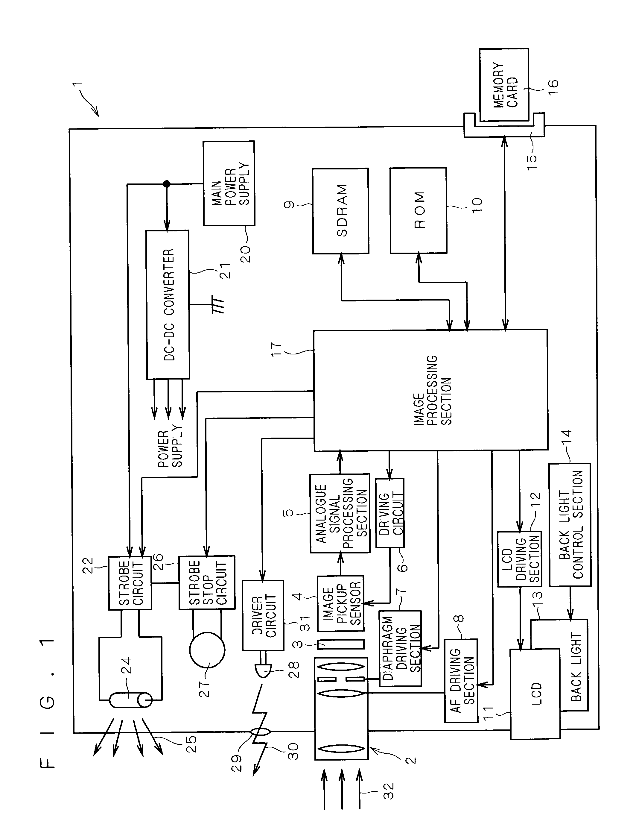
[0078]FIG. 1 is a schematic view showing the entirety of a digital still camera 1 equipped with an AF control apparatus according to the first embodiment of the present invention.

[0079]First a configuration of the digital still camera 1 is briefly explained, and then the AF control apparatus according to the first embodiment will be described in detail. The digital still camera 1 comprises: an optical mechanism 2 having lens group, a diaphragm mechanism and the like; an optical LPF (low-pass filter) 3; an image pickup sensor 4 such as CCD or CMOS; a driving circuit 6 for driving the image pickup sensor 4; an analogue signal processing section 5; and an image processing section 17. Reflected light 32 from a subject having passed through the optical mechanism 2 and the optical LPF 3 is detected by the image pickup sensor 4 having CCD (charge-coupled device) or CMOS, and outputted to the analogue signal processing section 5.

[0080]Though not clearly shown in the drawing, the analogue si...

second embodiment

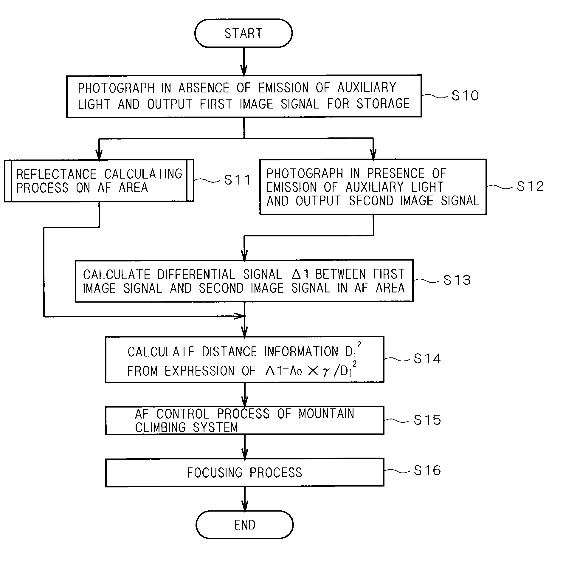
[0094]Next, the second embodiment of the present invention will be explained. In the above first embodiment 1, since the distance information D1, . . . , Dn stored in the distance data base 47 is calculated under the condition that the reflections of the subject and the background are constant (average (usual) reflectance), it is difficult to obtain correct distance information D1 when the main subject does not have an average reflectance. For solving this problem, the AF control apparatus according to the second embodiment provides means for automatically calculating the reflectance of the subject or the background, as well as provides distance measuring means not relying on the above distance data base 47.

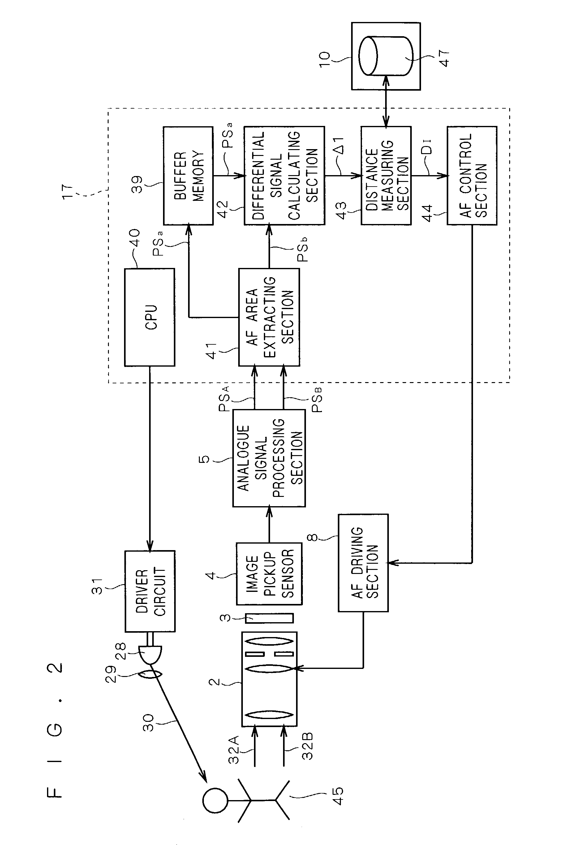
[0095]FIG. 5 is a schematic view showing an AF control apparatus according to the second embodiment mounted in the digital still camera 1, and FIG. 6 is a flow chart showing an AF control method thereof. As shown in FIG. 5, the AF control apparatus according to the second embodim...

third embodiment

[0103]Next, in the third embodiment, another example of the process of calculating reflectance of AF area (step S11) will be explained. In the second embodiment as described above, the calculated reflectance of the shade part of the subject is smaller than that of the part where a shade does not occur, which deteriorates the accuracy of distance information D1. The third embodiment takes influence of such a shade part into account and provides correcting means of reflectance γ.

[0104]As described in the second embodiment, the reflectance calculating section 48 calculates a reflectance γ without taking shade part included in the image signal PSA into account. In the third embodiment, it is to be assumed that an AF area is formed of matrix arrangement of a plurality of small blocks (image areas) of about 3×3 pixels to 5×5 pixels. The reflectance calculating section 48 acquires from the reflectance data base 49, a probability of occurrence of the event when each small block in that AF a...


PUM


Abstract

A CPU performs a control for photographing a main subject in absence of auxiliary light, whereby an image signal is outputted from an analogue signal processing section. Next, the CPU performs a control for photographing the main subject in presence of the auxiliary light, whereby an image signal is outputted from the analogue signal processing section. An AF area extracting section extracts image signals in an AF area from the image signals. A differential signal calculating section outputs a differential signal between the extracted image signal, and a distance measuring section compares magnitudes of that differential signal and a reference value in a distance data base to calculate distance information based on the comparison result. An AF control section executes AF control of mountain climbing system with the use of the distance information.

Description

BACKGROUND OF THE INVENTION[0001]1. Field of the Invention[0002]The present invention relates to an AF control apparatus which illuminates a subject with an auxiliary light, receives a reflection light from the subject to calculate distance information to the subject, and executes AF (automatic focusing) control, and an AF control method.[0003]2. Description of the Background Art[0004]In digital cameras such as digital video cameras and digital still cameras, light that has passed through an optical system having a variety of lens, for example, and formed an image (hereinafter, referred to as TTL light; TTL is an abbreviation for “through the lens.”) is detected by an image pickup sensor having an image pickup device such as CCD and CMOS, and subjected to various image processings after converted to a digital image signal (raw image data) by A / D conversion. The image data having subjected to these image processings is then displayed on an EVF (electronic view finder) or subjected to...

Claims


Application Information

Patent Timeline
Patent Type & Authority Patents(United States)
IPC IPC(8): H04N5/232G01C3/06G02B7/28G02B7/32G03B13/36H04N5/225
CPCH04N5/2256H04N5/23212H04N23/56H04N23/671
Inventor SASAKI, GEN
Owner MEGACHIPS
Why Eureka
Try Eureka