Compact multi-axis interferometer

a multi-axis interferometer and compact technology, applied in the field of compact multi-axis interferometers, can solve the problems of difficult to manufacture such large optical-quality elements, difficult to accommodate large measurement mirrors in confined spaces, and high cost of fabrication

Inactive Publication Date: 2007-05-29
AGILENT TECH INC
View PDF13 Cites 36 Cited by
  • Summary
  • Abstract
  • Description
  • Claims
  • Application Information

AI Technical Summary

Benefits of technology

[0014]In accordance with an aspect of the invention, a multi-axis interferometer uses a shared measurement beam for a first reflection from a measurement mirror and then splits the shared measurement beam into multiple individual beams for second reflections corresponding to the measurement axes of the interferometer. The reference beam similarly remains a shared beam until after a first reflection from the reference reflector when the shared reference beam is split into individual beams. Accordingly, a multi-axis interferometer having N measurement axes requires only N+1 beam paths to the measurement mirror instead of 2N beam paths as required in some prior interferometers. The reduction in the number of measurement beam paths (and reference beam paths) allows a compact interferometer architecture.

Problems solved by technology

However, a large measurement mirror is difficult to accommodate in confined spaces such as may be found in semiconductor manufacturing equipment.
The fabrication of such large optical-quality elements can be expensive and difficult.

Method used


Image

  • Compact multi-axis interferometer
  • Compact multi-axis interferometer
  • Compact multi-axis interferometer

Examples


Embodiment Construction

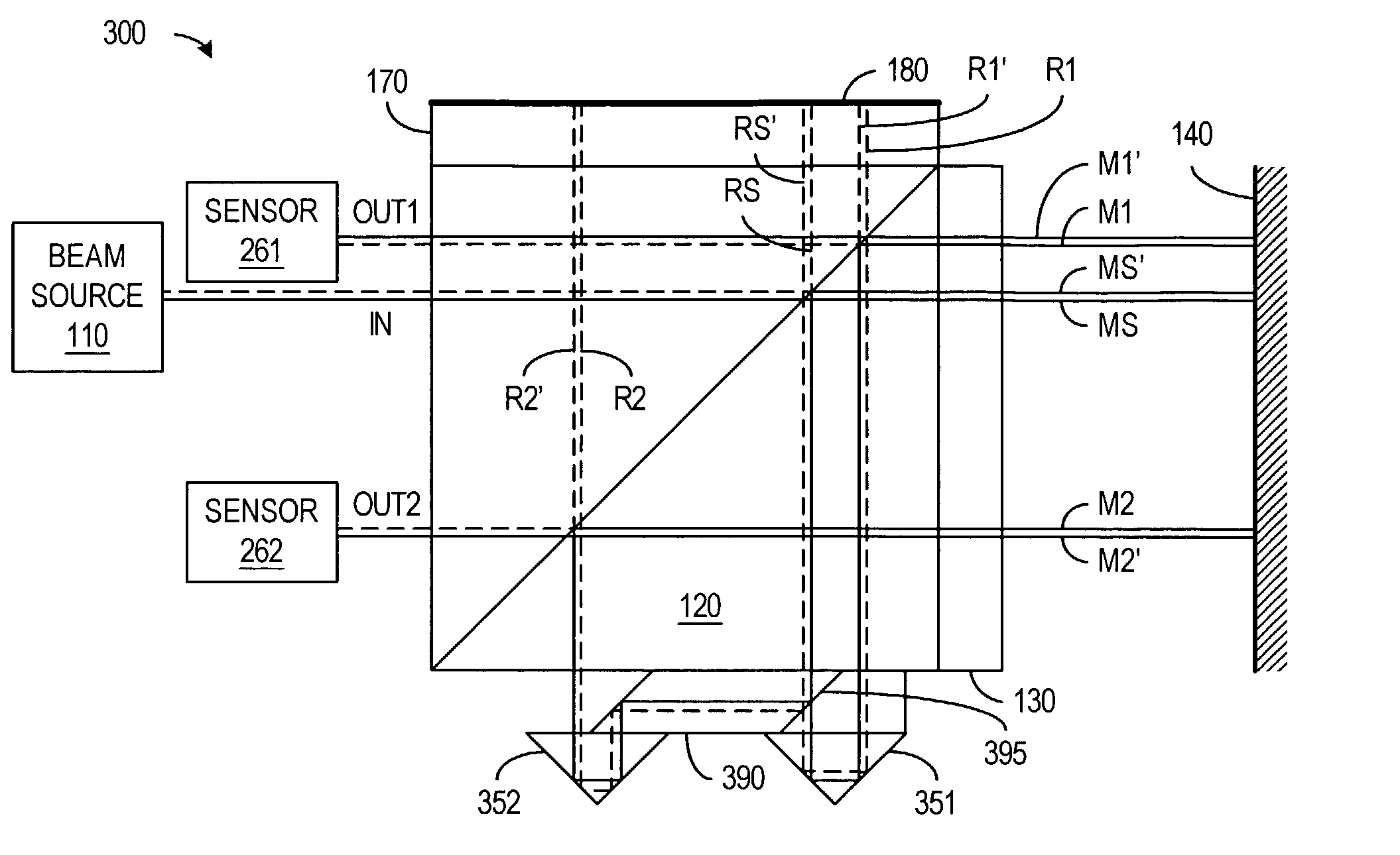
[0025]In accordance with an aspect of the invention, a multi-axis interferometer uses a shared measurement path and a shared reference path for first reflections of shared measurement and reference beams respectively from the measurement and reference reflectors. After the shared paths, beam-splitting optics split the shared measurement beam and the shared reference beam into multiple individual beams corresponding to respective measurement axes. This interferometer architecture has a small number of beam paths permitting implementation of compact optics for multi-axis interferometers.

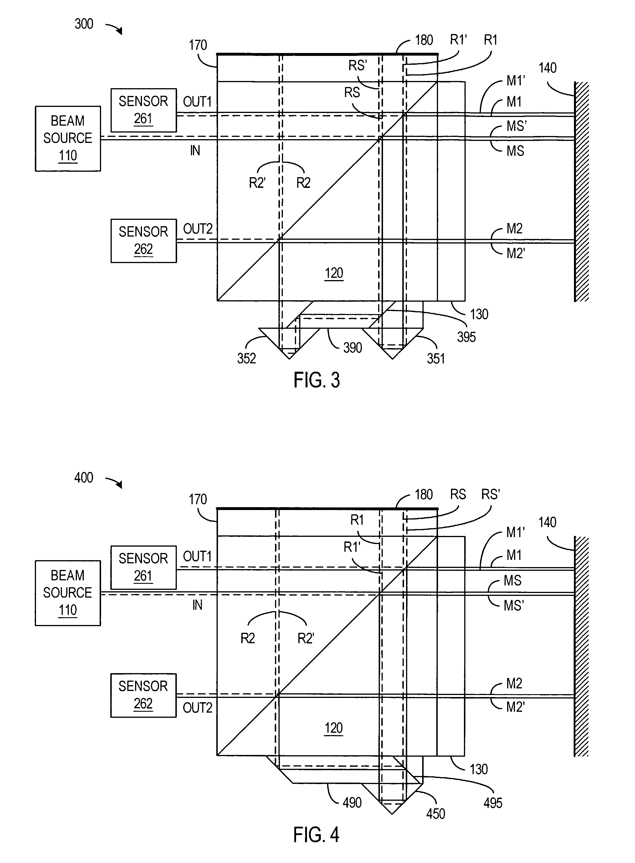
[0026]FIG. 3 illustrates a two-axis interferometer 300 in accordance with an embodiment of the invention. Interferometer 300 includes a beam source 110, a polarizing beam splitter 120, quarter-wave plates 130 and 170, a measurement reflector 140, a reference reflector 180, retroreflectors 351 and 352, and beam-splitting optics 390.

[0027]Beam source 110 such as a laser produces a single input beam IN in...


PUM


Abstract

A multi-axis plane mirror interferometer uses shared measurement and reference beams that respectively reflect from measurement and reference reflectors before that shared beams are split into individual beams corresponding to the measurement axes of the interferometer. An N-axis interferometer thus requires only N+1 measurement beam paths, one for the shared measurement beam and N for individual measurement beams, to provide for each measurement axis the two reflections that cancel angular misalignment between the measurement and reference reflectors.

Description

BACKGROUND[0001]Interferometers are precision tools that can accurately measure the position and / or the velocity of a target device. For such measurements, a measurement mirror is generally mounted on the target device. In semiconductor device manufacturing equipment, for example, the measurement mirror can be mounted on a precision stage to permit an interferometer to precisely measure the movement of the stage while the stage positions a wafer for processing.[0002]The measurement mirror of an interferometer generally needs to be aligned with the interferometer optics that direct a measurement beam at the measurement mirror. Plane mirror interferometers use a planar measurement mirror, which provides a uniform target area so that alignment of the position of the measurement mirror is less critical than in some other types of interferometers. Alignment tolerances for the orientation of the measurement mirror in a plane mirror interferometer can also be relaxed through use of interfe...

Claims


Application Information

Patent Timeline
Patent Type & Authority Patents(United States)
IPC IPC(8): G01B11/02G01B9/02
CPCG01B9/02027G01B9/02049G01B9/02061G01B9/02018G01B2290/70G01B2290/15G01B2290/45
Inventor RAY, ALAN B.
Owner AGILENT TECH INC
Why Eureka
Try Eureka