Engine motion active control

a technology of active control and engine, which is applied in the direction of combustion engines, machines/engines, output power, etc., can solve the problems of increased nvh, noise and vibration that is noticeable by the vehicle operator, and vibrations induced in the engine and the rest of the powertrain

Active Publication Date: 2007-06-05
GM GLOBAL TECH OPERATIONS LLC
View PDF2 Cites 32 Cited by
  • Summary
  • Abstract
  • Description
  • Claims
  • Application Information

AI Technical Summary

Problems solved by technology

Under certain conditions, a dynamic (AC) torque is generated, and can result in noise and vibration that is noticeable by the vehicle occupants.
For example, vibrations are induced in the engine and the remainder of the powertrain as a result of the combustion process.
The reduced vibration frequency in the deactivated mode can result in an increase in NVH, which may be noticeable by the vehicle operator.

Method used


Image

  • Engine motion active control
  • Engine motion active control
  • Engine motion active control

Examples


Embodiment Construction

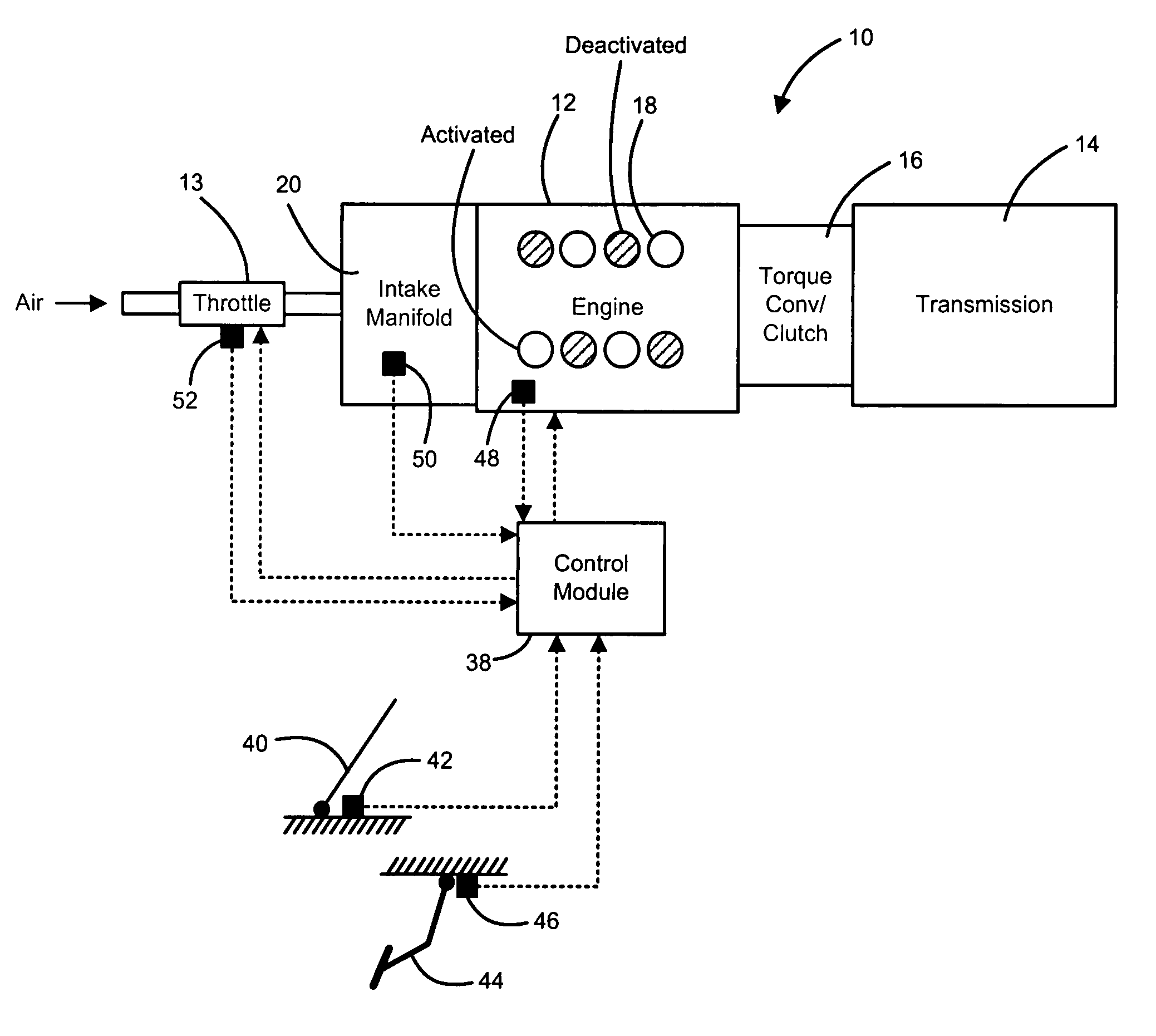
[0022]The following description of the preferred embodiment is merely exemplary in nature and is in no way intended to limit the invention, its application, or uses. For purposes of clarity, the same reference numbers will be used in the drawings to identify similar elements. As used herein, the term module refers to an application specific integrated circuit (ASIC), an electronic circuit, a processor (shared, dedicated, or group) and memory that execute one or more software or firmware programs, a combinational logic circuit, and / or other suitable components that provide the described functionality. As used herein, activated refers to operation using all of the engine cylinders. Deactivated refers to operation using less than all of the cylinders of the engine (one or more cylinders not active).

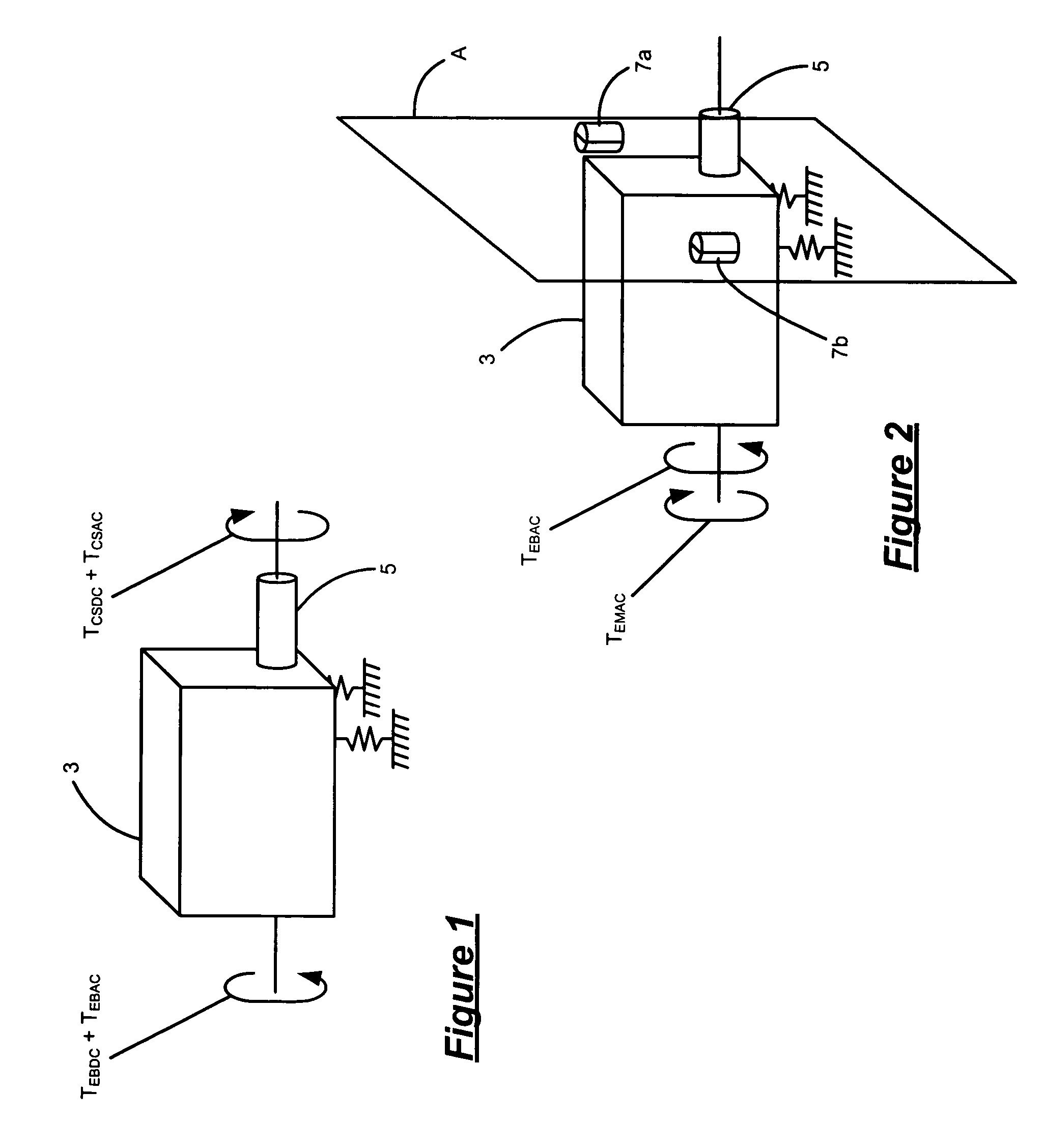
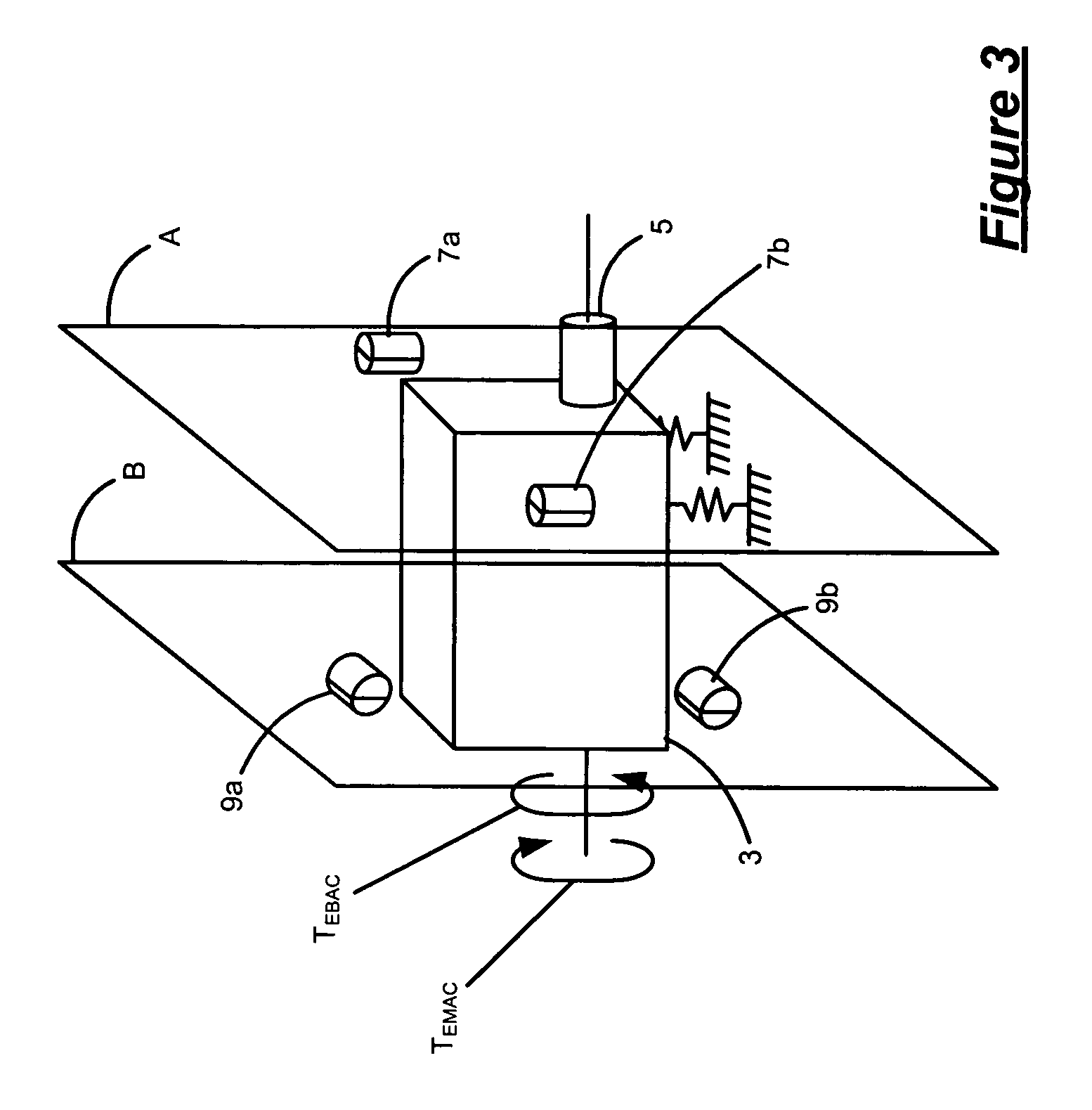
[0023]Referring now to FIG. 1, a schematic engine 3 includes a crankshaft 5. As discussed in further detail below, the engine 3 generates crankshaft torque that includes both a dynamic (AC) ...


PUM


Abstract

An engine active motion control system for controlling engine dynamic torque includes an engine that generates a first dynamic torque. A first module selectively initiates generation of a second dynamic torque about an axis of rotation of a crankshaft of the engine in a direction opposite that of the first dynamic torque generated through the crankshaft.

Description

CROSS-REFERENCE TO RELATED APPLICATIONS[0001]This application claims the benefit of U.S. Provisional Application No. 60 / 692,432, filed on Jun. 21, 2005. The disclosure of the above application is incorporated herein by reference.FIELD OF THE INVENTION[0002]The present invention relates to engine noise, vibration and harshness (NVH), and more particularly to active engine block dynamic combustion torque cancellation.BACKGROUND OF THE INVENTION[0003]Internal combustion engines create drive torque that is transferred to a drivetrain via a crankshaft. The crankshaft torque and engine block dynamic combustion torque are generally equal in amplitude and opposite in direction. Engines are designed to produce a steady-state (DC) torque. Under certain conditions, a dynamic (AC) torque is generated, and can result in noise and vibration that is noticeable by the vehicle occupants.[0004]Some internal combustion engines include engine control systems that deactivate cylinders under low load sit...

Claims


Application Information

Patent Timeline
Patent Type & Authority Patents(United States)
IPC IPC(8): F02B75/06F02D13/06
CPCF02D13/06F02D17/02Y02T10/18Y02T10/12
Inventor HOHNSTADT, FREDERICK P.TERVO, STEVEN A.JACOBSON, ERIC N.FERRARI, BRIAN E.ELZINGA, JR., DONALD R.DEFENDERFER, ERIC J.WISE, SCOTTBORS, WOLFGANGFARIBORZI, BORZ
Owner GM GLOBAL TECH OPERATIONS LLC
Why Eureka
Try Eureka