
Piezo-electric speaker

Inactive Publication Date: 2007-06-05
KOBAYASHI FUJIHIKO
View PDF8 Cites 3 Cited by
  • Summary
  • Abstract
  • Description
  • Claims
  • Application Information

AI Technical Summary

Benefits of technology

[0006]It is, therefore, an object of the present invention to provide a piezo-electric speaker which can ensure a uniform sound in a broad band and can easily reproduce a signal of large amplitude or sound.
[0008]According to this embodiment, since the piezo-electric vibration plate is divided into parts of any configuration, the distortion cannot be easily caused when the vibration plate vibrates and thus it is possible to ensure a uniform sound in a broad band and to easily reproducing a signal of large amplitude or sound.
[0010]According to this embodiment, since the piezo-electric vibration plate is divided by dividing slits, the distortion cannot be easily caused when the vibration plate vibrates. The vibration can be efficiently propagated from the center of the piezo-electric member to the periphery. Thus it is possible to ensure a uniform sound in a broad band and to easily reproducing a signal of large amplitude or sound.

Problems solved by technology

This makes it difficult to ensure a uniform sound in a broad band.
Since the diameter of the piezo-electric vibration plate 42 is limited, a large distortion of the piezo-electric vibration plate is caused when a signal of large sound is applied and therefore it is difficult to reproduce a clear sound.

Method used


Image

  • Piezo-electric speaker
  • Piezo-electric speaker
  • Piezo-electric speaker

Examples


Embodiment Construction

[0023]The following description of the preferred embodiment(s) is merely exemplary in nature and is in no way intended to limit the invention, its application, or uses.

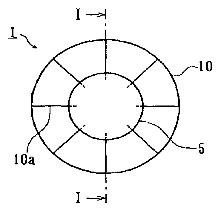
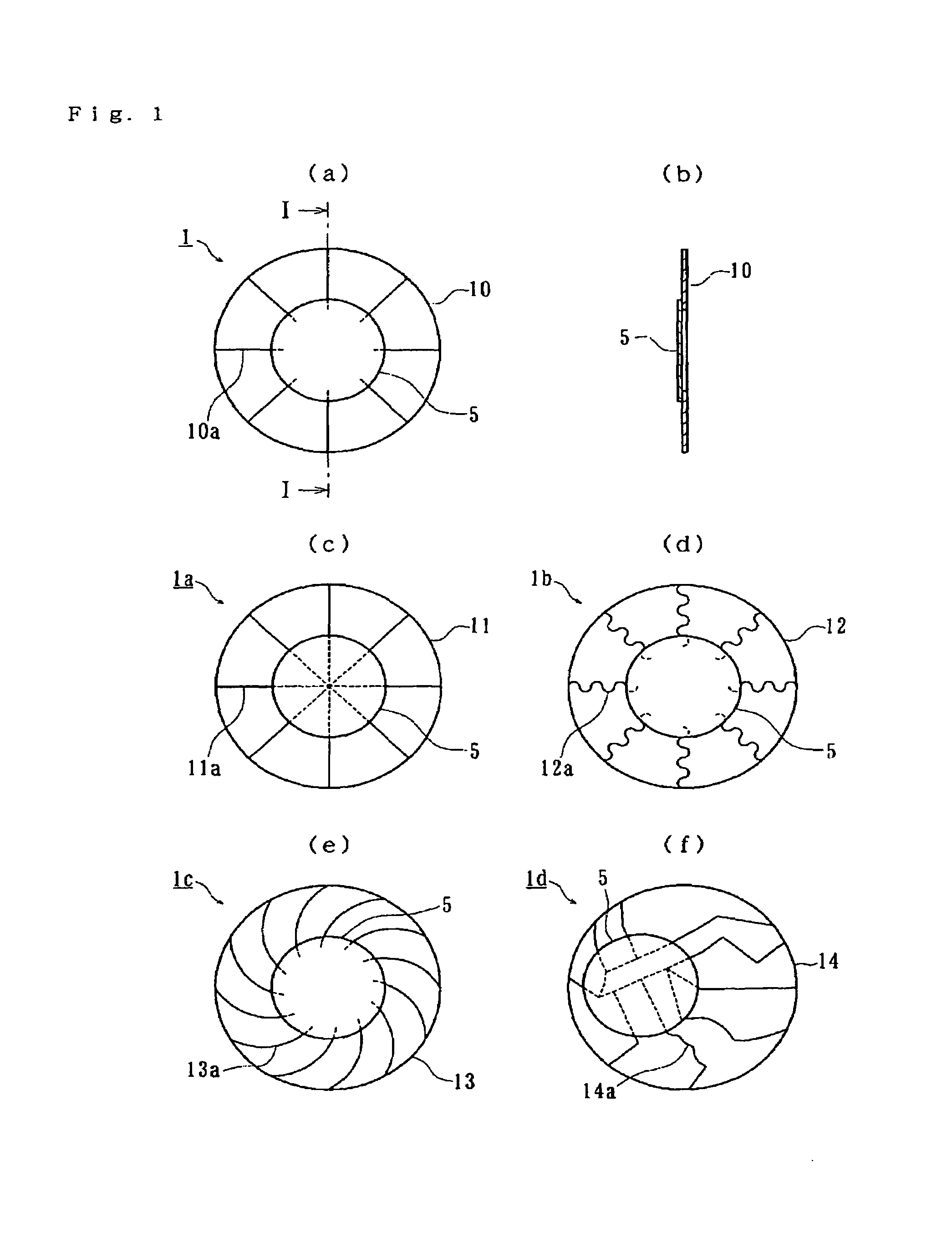
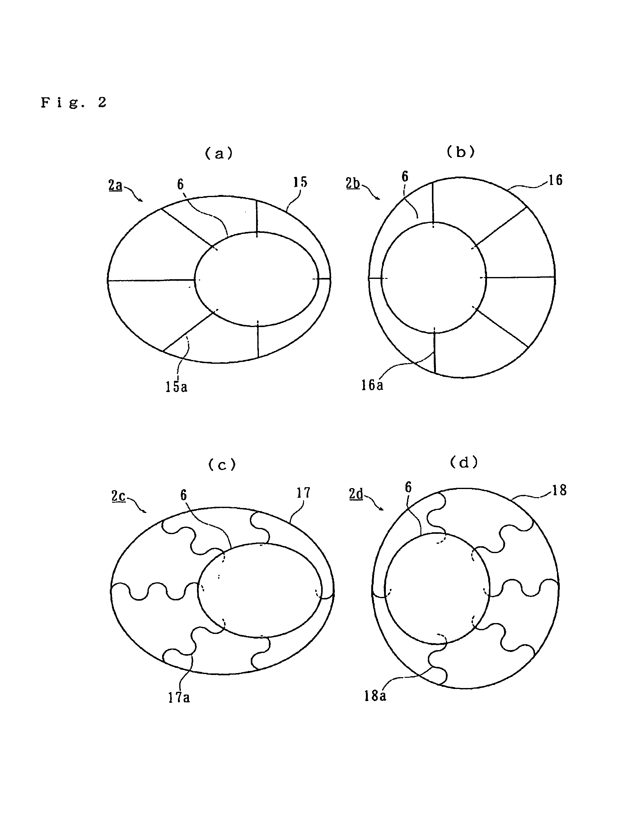
[0024]A piezo-electric speaker 1 shown in FIGS. 1˜8 is connected to audio instruments such as CD players or MD players generally used in homes for producing a sound. The piezo-electric speaker 1 comprises a piezo-electric member 5 and piezo-electric vibration plate 10 as shown in FIGS. 1(a) and (b). The piezo-electric member 5 is formed as a disc of piezo-electric ceramic generating the mechanical distortion based upon the application of electric signals. The piezo-electric vibration plate 10 is a metallic disc having a larger area than that that of the piezo-electric member 5. The piezo-electric vibration plate 10 is formed with dividing slits 10a radially extending from the periphery toward the center of the vibration plate 10. In the embodiments in which both the piezo-electric member 5 and the piezo-electric vibra...


PUM


Abstract

A piezo-electric speaker ensures a uniform sound in a broad band and can easily reproduce a signal of large amplitude or sound. A piezo-electric speaker has a piezo-electric member to generate a vibration according to an electric signal applied thereto. A piezo-electric vibration plate converts the vibration to a sound. The piezo-electric vibration plate is positioned closely to the piezo-electric member. The piezo-electric vibration plate is divided into parts of any configuration and is connected to the piezo-electric member.

Description

CROSS-REFERENCE TO RELATED APPLICATIONS[0001]This application claims priority to Japanese Patent Application Nos. 2001-272907 filed Sep. 10, 2001 and 2002-215376 filed Jul. 24, 2002, which applications are herein expressly incorporated by reference.FIELD OF THE INVENTION[0002]The present invention relates to a piezo-electric speaker having a piezo-electric member.BACKGROUND OF THE INVENTION[0003]A piezo-electric speaker 40 of the prior art has, as shown in FIG. 10, has a completely round piezo-electric member 41 generating a vibration according to an electric signal applied thereto. A piezo-electric vibration plate 42 is adhered to the piezo-electric member 41 to convert the vibration to a sound. The piezo-electric member 41 and the piezo-electric vibration plate are adhered to each other with the centers of them being aligned.[0004]However in the piezo-electric speaker 40 of the prior art, since the piezo-electric vibration plate 42 is made of a metallic plate-shaped member with le...

Claims


Application Information

Patent Timeline
IPC IPC(8): H04R25/00H04R7/02H04R7/04H04R17/00
CPCH04R17/00H04R17/005
Inventor KOBAYASHI, FUJIHIKO
Owner KOBAYASHI FUJIHIKO
Learn More