Recording apparatus and method, and reproducing apparatus and method

a technology of recording apparatus and reproducing apparatus, which is applied in the field of recording apparatus and method, reproducing apparatus and method, can solve the problems of adversely affecting until the right edge of the screen, screen cannot be equally updated, so as to achieve secure decoding

Inactive Publication Date: 2007-06-05
SONY CORP
View PDF13 Cites 2 Cited by
  • Summary
  • Abstract
  • Description
  • Claims
  • Application Information

AI Technical Summary

Benefits of technology

[0033]According to claims 6, 10, 11, and 15 of the present invention, since at least part of information of a header is recorded to a system area that can be almost securely reproduced in the high speed reproducing operation, even if the header portion cannot be reproduced, the reproduced data can be decoded. According to claim 16 of the present invention, since information of a header is the same in all frames and at least part of information of the header is recorded to the system area, the reproduced data can be more securely decoded in the high speed reproducing operation.

Problems solved by technology

Thus, the screen cannot be equally updated.
In addition, since the position on the tape cannot be predicted, if a tape pattern is traced at predetermined intervals, the screen cannot be equally updated.
Moreover, if at least one error takes place, it adversely affects until the right edge of the screen.
Thus, until the next slice header is detected, the error continues.
However, when a GOP is composed of for example 15 frames, the editing unit is too large.
However, when an MPEG stream contains a predictive picture that requires an earlier picture or both an earlier picture and a later picture for decoding the predictive picture, it becomes impossible to perform the editing process for each frame.
However, in the high speed reproducing operation whose tape speed is higher than the recording operation (for example, twice or higher), since data of the tape is fragmentarily reproduced, if information of the header is changed for each frame, a problem takes place.
Thus, if the header of frame 1 is different from the header of picture data of another frame, frame 1 cannot be correctly decoded.

Method used


Image

  • Recording apparatus and method, and reproducing apparatus and method
  • Recording apparatus and method, and reproducing apparatus and method
  • Recording apparatus and method, and reproducing apparatus and method

Examples


Embodiment Construction

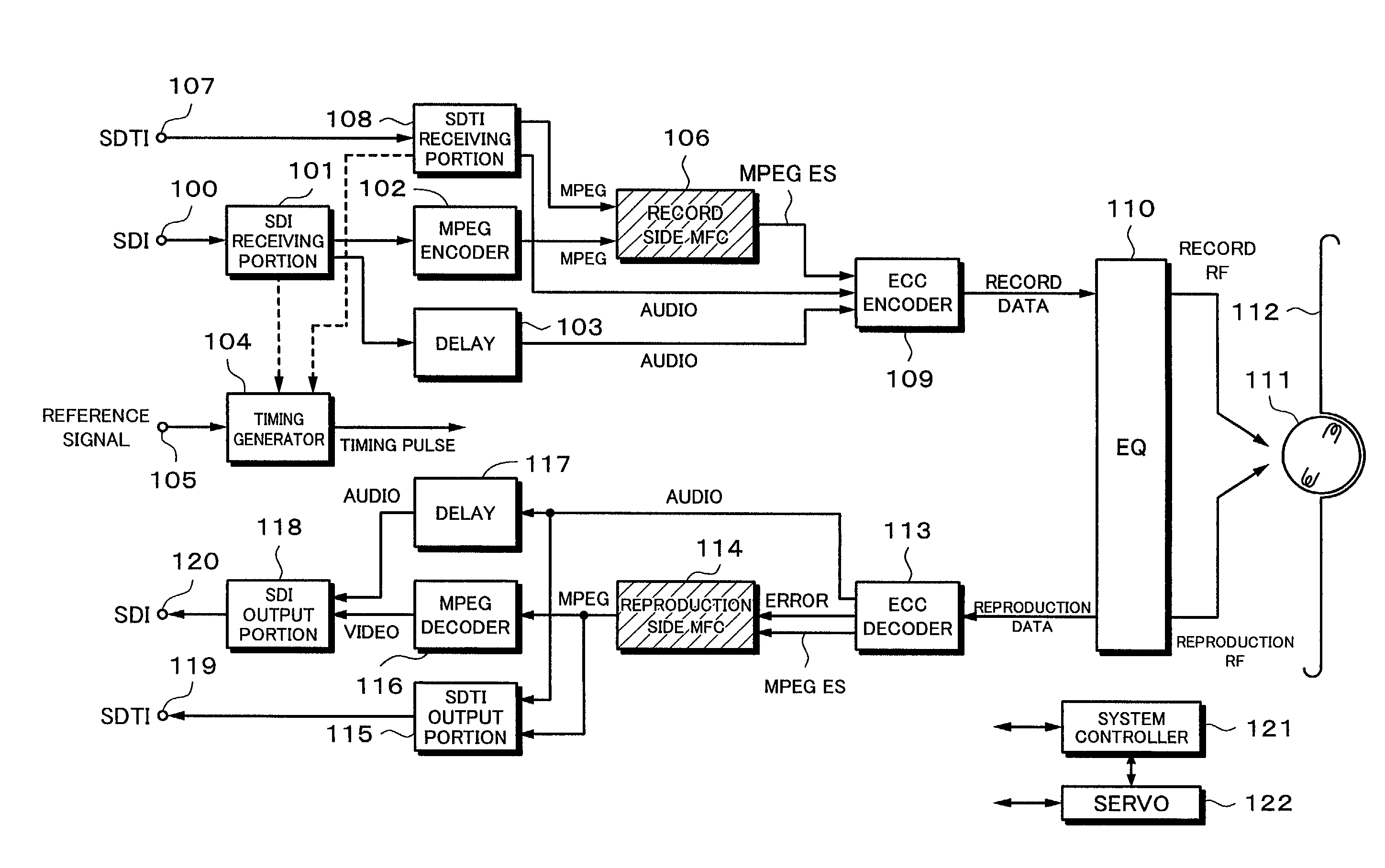
[0060]Next, an embodiment of the present invention will be described. The embodiment is applied to a digital VTR. The embodiment is suitable for the environment of a broadcasting station.

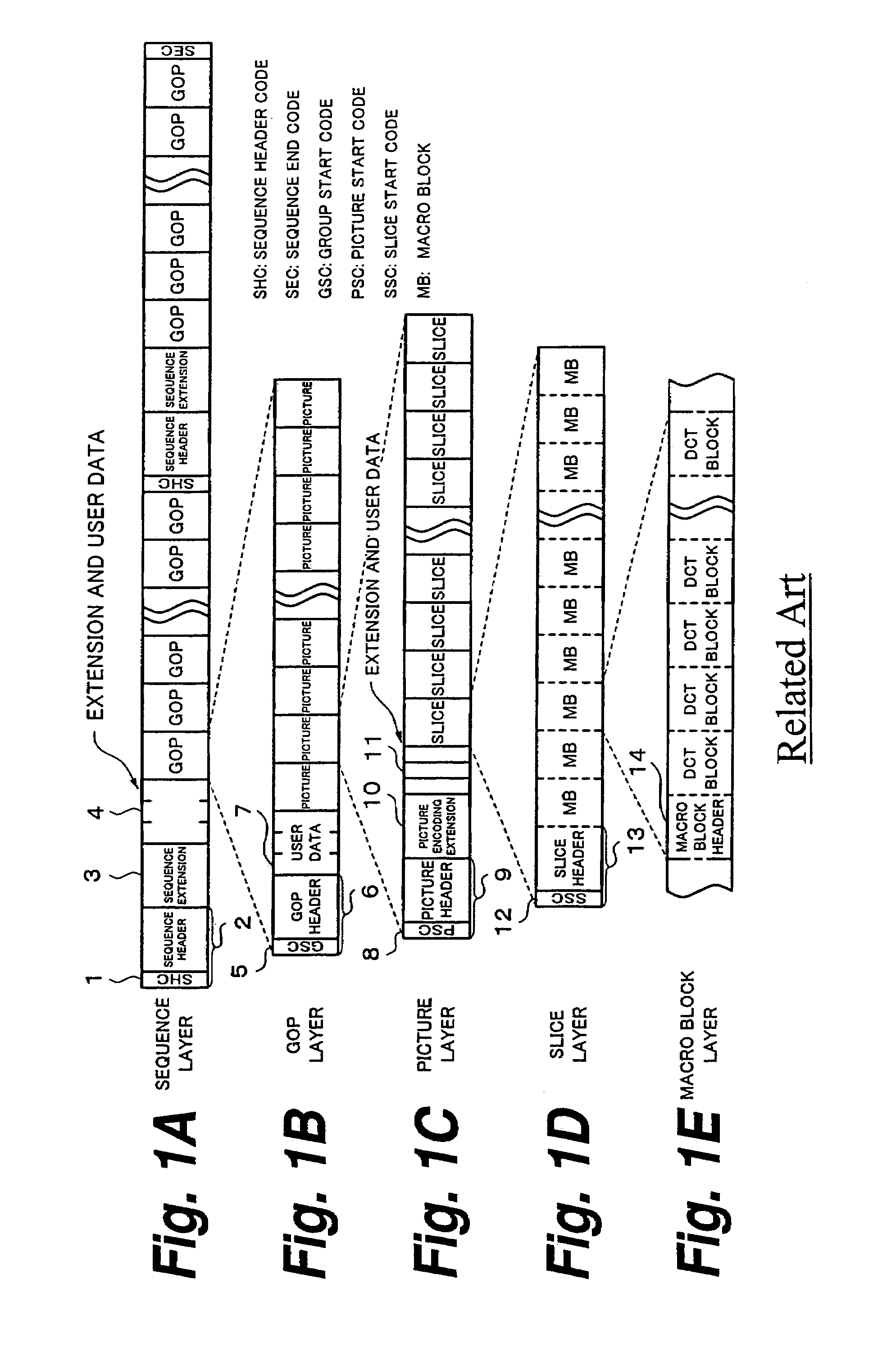
[0061]According to the embodiment, for example MPEG2 is used as a compression formation. The MPEG2 is a combination of a motion compensation predictive encoding and a compression encoding using DCT. MPEG2 data is hierarchically structured. As shown in FIG. 1, MPEG2 data is composed of a macro block layer (FIG. 1E) as the lowest layer, a slice layer (FIG. 1D), a picture layer (FIG. 1C), a GOP layer (FIG. 1B), and a sequence layer (FIG. 1A) as the highest layer.

[0062]As shown in FIG. 1E, the macro block layer is composed of DCT blocks each of which is a data unit for DCT. The macro block layer is composed of a macro block header and a plurality of DCT blocks. As shown in FIG. 1D, the slice layer is composed of a slice header portion and at least one macro block. As shown in FIG. 1C, the picture layer ...


PUM


Abstract

A selector has both a function for creating a header of a sequence layer and a header of a picture layer corresponding to reproduced data of a system area and a function for outputting one of an input stream and a stream of which a created header has been added to the header of the input stream as an output stream. When the mode is not high speed reproducing mode, the selector outputs the header contained in the input stream as a header of the output stream. When the mode is high speed reproducing mode, a header (the header of the sequence layer and the header of the picture layer) is created corresponding to data reproduced from the system area. The selector outputs an output stream of which the created header has been added to the input stream.

Description

TECHNICAL FIELD[0001]The present invention relates to a recording apparatus and a recording method for recording a digital video signal to a tape shaped record medium and also to a reproducing apparatus and a reproducing method for reproducing a digital video signal from a tape shaped record medium.BACKGROUND ART[0002]As exemplified with a digital VTR (Video Tape Recorder), a data recording and reproducing apparatus that records a digital video signal and a digital audio signal to a record medium and reproduces them therefrom is known. Since the data capacity of a digital video signal is huge, conventionally, it is compression-encoded corresponding to a predetermined method and then the encoded data is recorded to a record medium. In recent years, MPEG2 (Moving Picture Experts Group phase 2) is known as a compression-encoding standard.[0003]In picture compression technologies such as the above-mentioned MPEG2, the data compression ratio is improved using variable length code. Thus, ...

Claims


Application Information

Patent Timeline
Patent Type & Authority Patents(United States)
IPC IPC(8): H04N7/26H04N5/91H04N5/783H04N7/30H04N7/52H04N9/79H04N9/804
CPCH04N5/783H04N9/8042H04N21/236H04N19/34H04N21/434H04N21/4342H04N19/46H04N21/23602H04N9/7921G11B20/00007
Inventor TOGASHI, HARUOSUGIYAMA, AKIRATODO, SHINMATSUMOTO, HIDEYUKI
Owner SONY CORP
Why Eureka
Try Eureka