Optical data recording medium and method for reproducing recorded data

Inactive Publication Date: 2008-06-05
SHARP KK
View PDF43 Cites 0 Cited by
  • Summary
  • Abstract
  • Description
  • Claims
  • Application Information

AI Technical Summary

Benefits of technology

[0015]The present invention is made in light of the foregoing problems. An object of the present invention is to provide an optical data recording medium in which a sign

Problems solved by technology

However, in the conventional optical data recording media, resolution limit is not enough.
In the example, a resin layer is used as the reproducing layer, and the resin is so adhesive that it is very difficult to attain a thin thickness of the resin layer.
Therefore, there is a limit in how thick the reproducing layer can be.
The arrangement in which the thickness of the reproducing layer is thin in view of the above limitation faces the following prob

Method used


Image

  • Optical data recording medium and method for reproducing recorded data
  • Optical data recording medium and method for reproducing recorded data
  • Optical data recording medium and method for reproducing recorded data

Examples


example 1

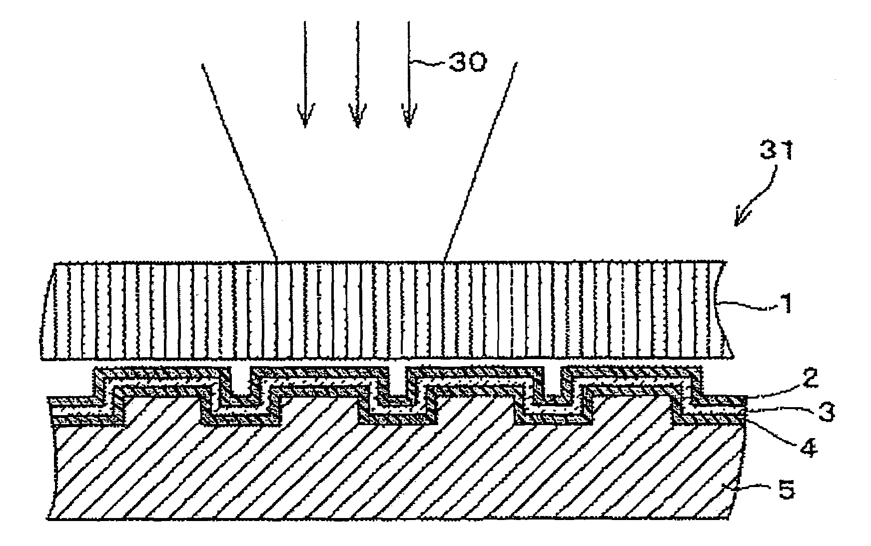
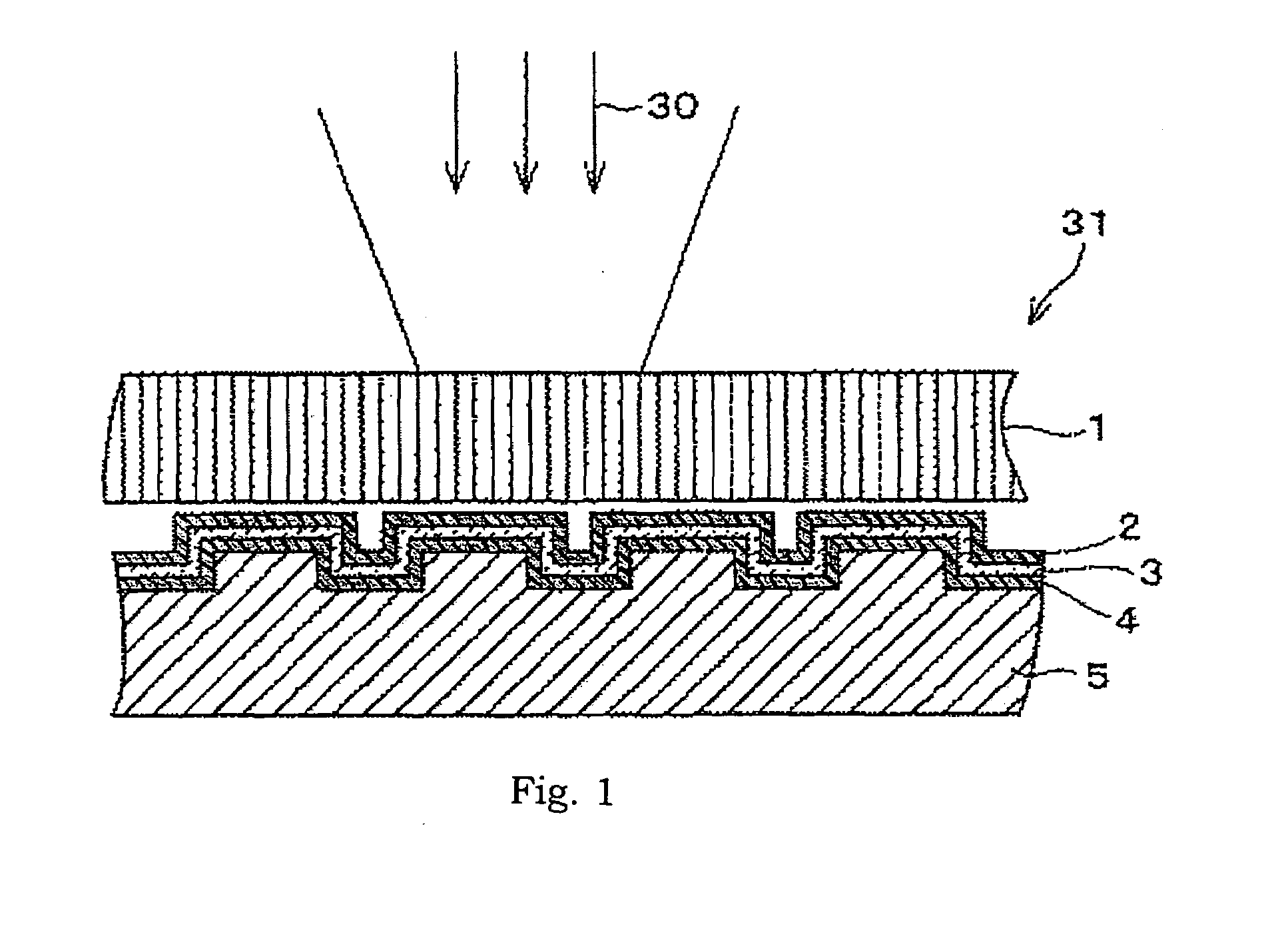
[0101]As an Example 1, an optical data recording medium having the following arrangement was produced (hereinafter, referred as “Example 1 disc”). As shown in the FIG. 1, pits creating a non-flat surface are provided on polyolefin-based resin substrate 5 having a 0.5 mm thickness. The pits corresponded to recorded data. On that surface of the polyolefin-based resin substrate 5 on which the pits are formed, an Al layer 4 (30 nm in thickness) used as a reflective layer, as Si layer 4 (50 nm in thickness) used as an light absorption layer, and a ZnO film 2 (225 nm in thickness) used as a reproducing layer were formed in this order. On a top surface of the reproducing layer 2, glass 1 (0.5 mm in thickness) as a cover layer was placed.

[0102]Also, as a Comparative Example, an optical data recording medium with following arrangement was produced (hereinafter referred as “conventional disc”). As shown in FIG. 4, pits creating a non-flat surface were provided on a polyolefin-based resin subs...

example 2

[0109]In Example 2, a material of the reproducing layer was examined.

[0110]An optical data recording medium (hereinafter Example 2 disc) used in Example 2 was identical with the Example 1 disc in the Example 1, except that the reproducing layer of the Example 2 disc was made of, instead of ZnO, SnO2. Correlation between mark lengths for signals, and qualities of the signals was measured for the Example 1 disc and Example 2 disc. The measurement was carried out as in Example 1. That is, the measurement of a C / N (appraisal standard of signal quality) of pits having 0.1 μm through 0.5 μm mark length (pit length) was carried out.

[0111]The results of the measurements of the Example 1 disc and the Example 2 disc are graphed in FIG. 6. In FIG. 6, the solid line is the result of the Example 1 disc, whereas the broken line is the result of the Example 2 disc. In FIG. 6, the horizontal axis shows the pit length, and the vertical axis is OTF (optical transfer function) showing C / N (appraisal s...


PUM


Abstract

An optical data recording medium, in which irradiation of a light beam is used for recording and/or reproducing data includes (i) a substrate having an a rise and/or a recess which are a light-incident surface, (ii) a reflective layer, provided on the light-incident surface of the substrate, for reflecting the light beam, (iii) a light absorption layer for converting, to heat, a light of the light beam to heat on the surface of the reflective layer, (iv) a reproducing layer, provided on the surface of the heat-light converting layer, having a transmittance that changes in accordance with a light intensity distribution of the light beam. The optical data recording medium is excellent in super-resolution property, and enables reproduction of a shorter mark length.

Description

FIELD OF THE INVENTION[0001]The present invention relates to (i) an optical data recording medium for recording or reproduction of data, and (ii) a method for reproducing data from the optical data recording medium.BACKGROUND OF THE INVENTION[0002]In order to obtain an optical data recording medium having bigger storage capacity, there has been a demand for a technique to record and reproduce a signal in accordance with a further shorter mark length (pit length) in the optical data recording medium. Recently, an optical data recording medium has been developed which enables reproduction of a signal from a mark having a mark length shorter than a mark length of resolution limit of an optical system of a reproducing apparatus. Hereinafter, the optical data recording medium is referred as a “super-resolution optical data recording medium.”[0003]The super-resolution optical data recording medium includes at least a reproducing layer and a reflective layer layered in this order on a subs...

Claims


Application Information

Patent Timeline
IPC IPC(8): G11B7/24G11B5/09G11B7/0045G11B7/005G11B7/007G11B7/013
CPCG11B7/24G11B7/243G11B7/257G11B2007/2571G11B2007/24304G11B2007/2432G11B7/258
Inventor TAJIMA, HIDEHARUTAKAMORI, NOBUYUKIMORI, GOYAMAMOTO, MASAKI
Owner SHARP KK
Why Eureka
Try Eureka