Electric toothbrush housing design

Inactive Publication Date: 2007-06-12
CHURCH & DWIGHT CO INC
View PDF33 Cites 34 Cited by
  • Summary
  • Abstract
  • Description
  • Claims
  • Application Information

AI Technical Summary

Problems solved by technology

And so, that device is not readily applicable to the field of electric toothbrushes, and particularly those that are directed for widespread retail sale to consumers.
A flat region may facilitate gripping of the housing since such region disrupts the otherwise smooth contour of the otherwise cylindric

Method used


Image

  • Electric toothbrush housing design
  • Electric toothbrush housing design
  • Electric toothbrush housing design

Examples


Embodiment Construction

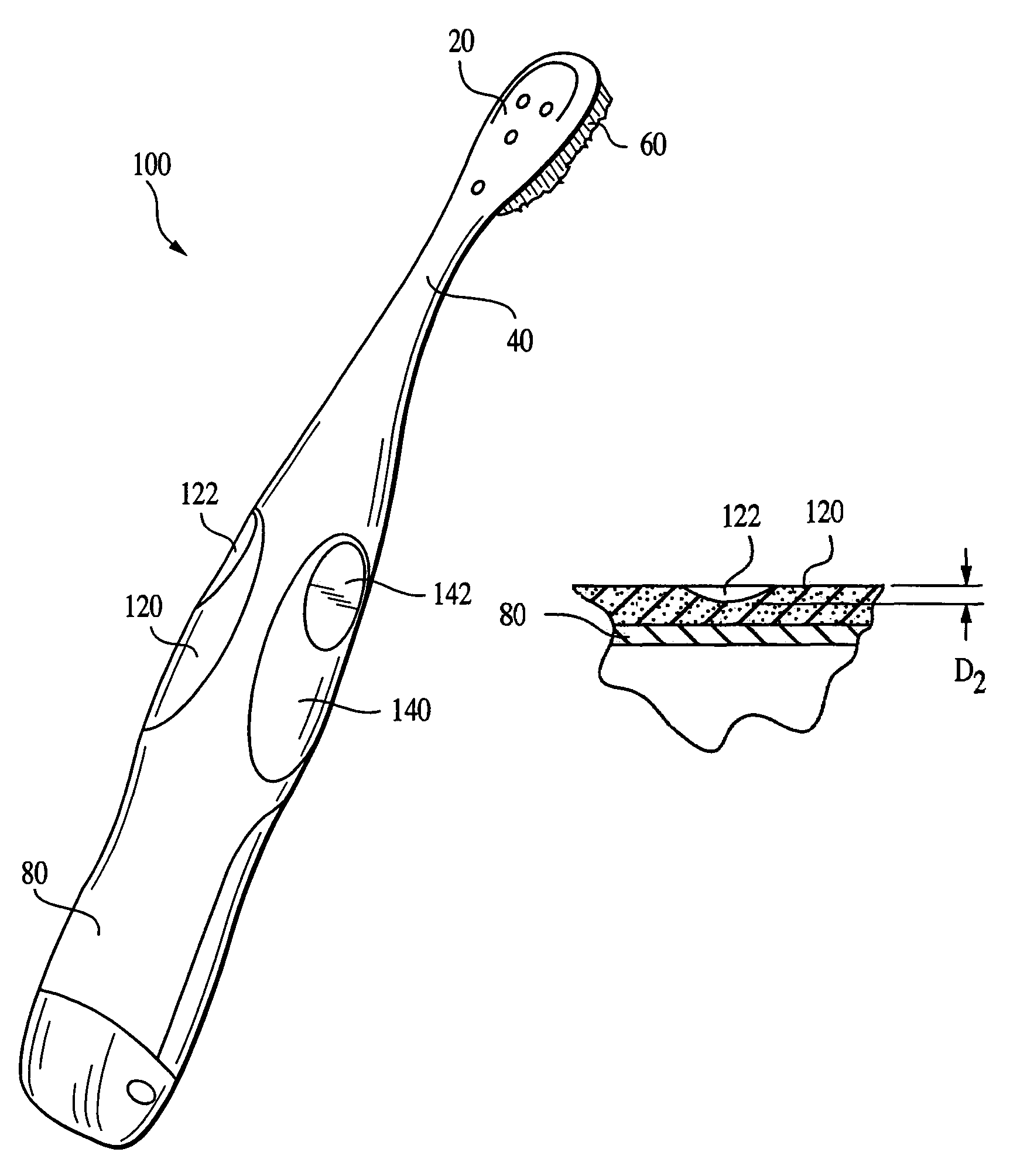
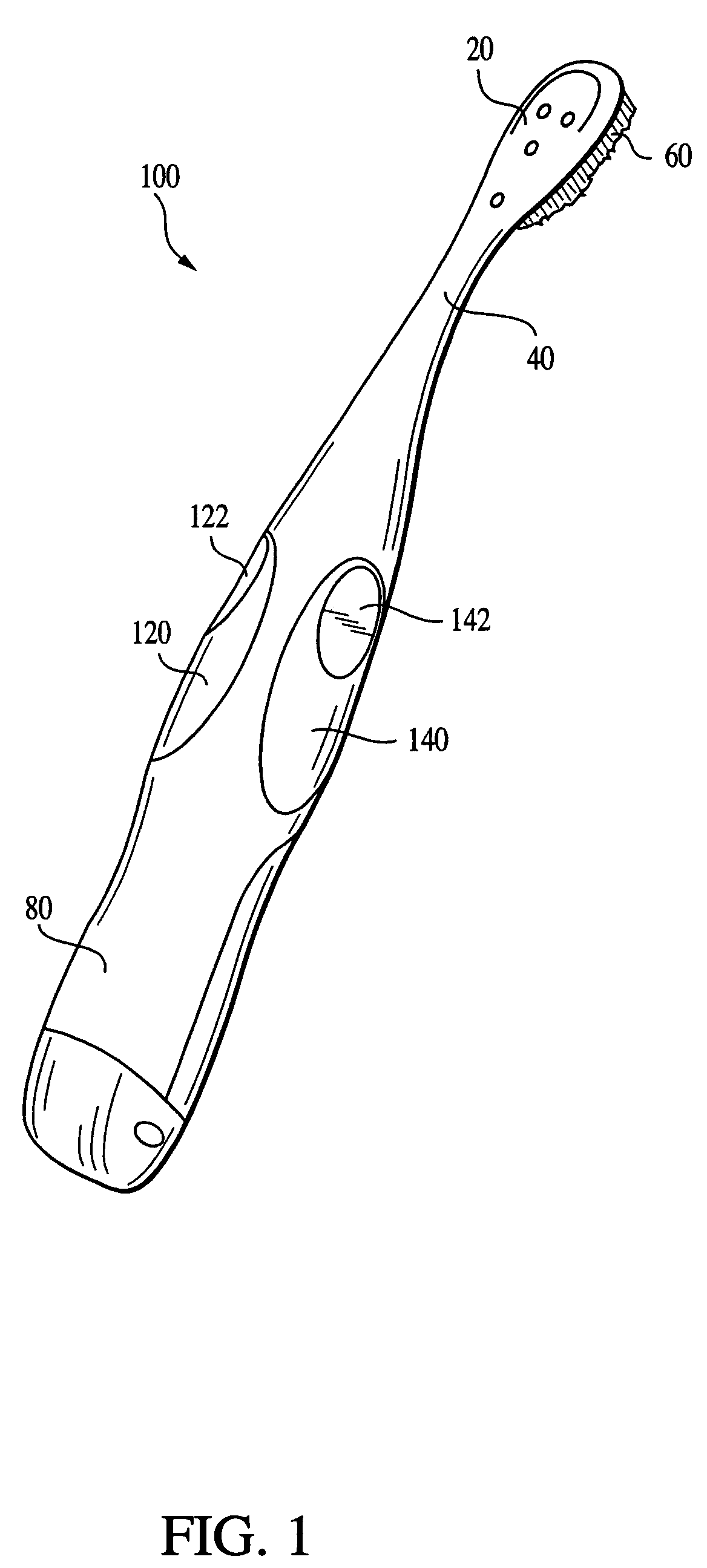
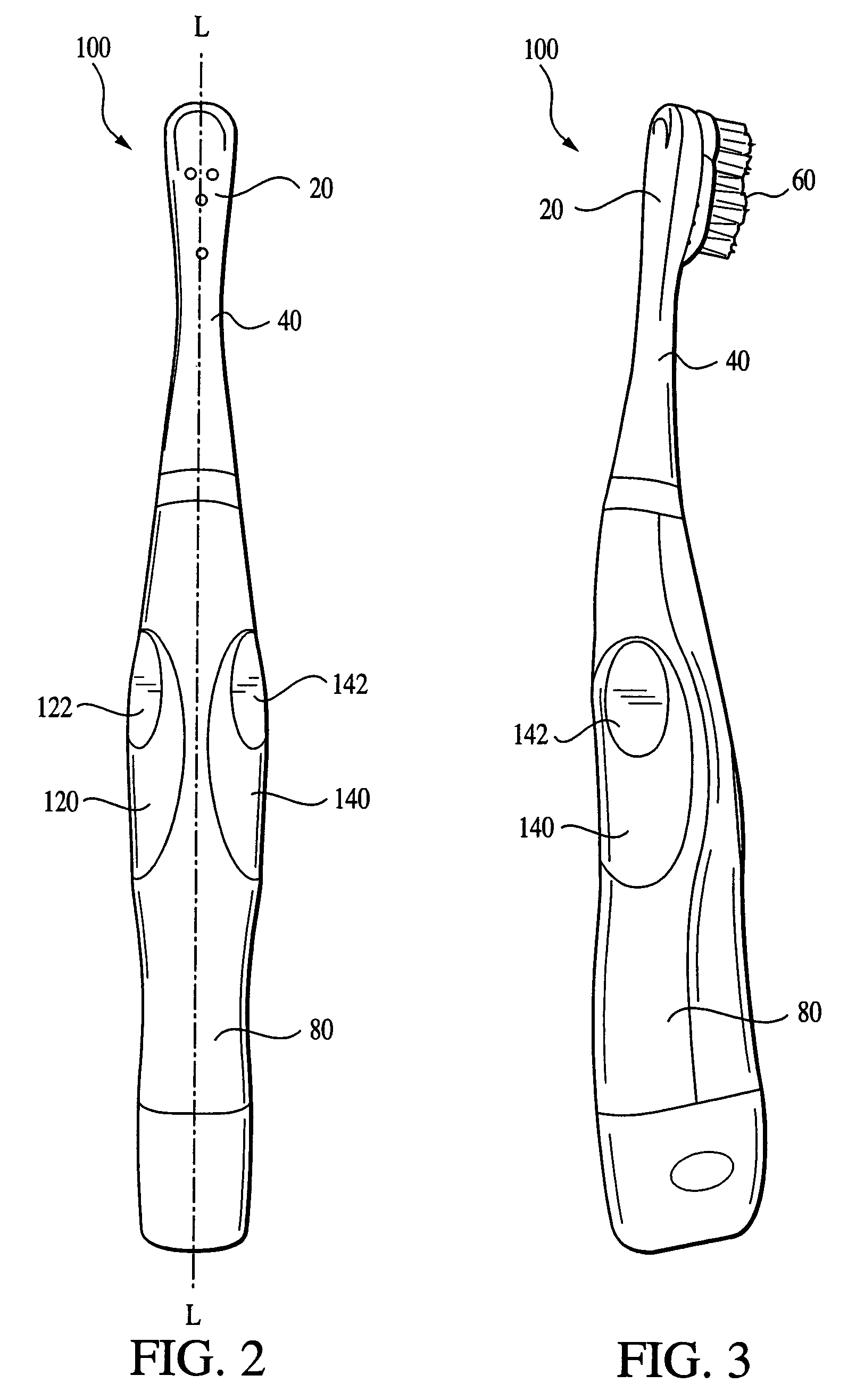
[0018]FIGS. 1–3 illustrate a preferred embodiment toothbrush 100 in accordance with the present invention. The preferred embodiment toothbrush 100 comprises a handle 80, a brush head 20, and a neck 40 extending therebetween and preferably integrally joined with both the handle 80 and the head 20. Disposed on the head 20 are a plurality of bristles 60. These bristles may include stationary bristles or movable bristles. By movable bristles, it is meant bristles that are powered or otherwise operatively engaged with a motor and drive mechanism generally housed within the body or handle 80 of the toothbrush. Disposed along the rear and lateral sides of the body of the toothbrush 100, preferably in the region of the handle 80 and / or the handle 80 and the neck 40, are two gripping members 120 and 140. These gripping members are formed of a softer material than the relatively rigid material forming the handle 80, neck 40, and brush head 20 of the toothbrush 100. A first gripping member 120...


PUM


Abstract

An improved housing for an electric toothbrush is disclosed. The improved housing provides two symmetrically positioned gripping members which assist the user in grasping the toothbrush particularly during brushing. Each of the gripping members includes a recessed gripping region having particular dimensional characteristics. The two gripping members are symmetrically arranged on the rearward sides of the toothbrush so that the brush may be used by both left-handed and right-handed individuals. A third gripping member may also be provided along the housing of the toothbrush.

Description

CROSS REFERENCE TO RELATED APPLICATION[0001]This application claims the benefit of U.S. Provisional Application No. 60 / 410,903, filed Sep. 13, 2002, the substance of which is incorporated herein by reference.FIELD OF THE INVENTION[0002]The present invention relates to electric toothbrushes and more particularly, improved housing designs for electric toothbrushes.BACKGROUND OF THE INVENTION[0003]Prior artisans have proposed a wide variety of designs for electric toothbrush housings and handles. Many of these designs provide a collection of ridges extending in a direction either parallel to the longitudinal axis of the housing, such as in U.S. Des. Pat. Nos. 375,204 and 454,251; or generally perpendicular to that axis as in 382,407. In addition to certain aesthetic qualities that a collection of parallel ridges may provide, providing such ridges may also serve to promote gripping of the housing by a user, particularly during use of the toothbrush. Although satisfactory in many respect...

Claims


Application Information

Patent Timeline
IPC IPC(8): A61C17/22A46B5/02A61C17/00A61C17/16
CPCA46B5/02A61C17/22A61C17/225A46B2200/1066A61C17/16
Inventor CHAN, JOHN GEOFFREYWHITNEY, JOHN ROYBROWN, PATRICK WILLIAM
Owner CHURCH & DWIGHT CO INC
Why Eureka
Try Eureka