Inline control valve with rack and pinion movement

a technology of inline control valve and rack and pinion, which is applied in the direction of valve details, valve arrangement, operating means/releasing devices, etc., can solve the problems of less attractive alternative, gas or stem flow noise, and liquid flow cavitation, and achieve the effect of convenient assembly and maintenan

Inactive Publication Date: 2005-09-29
LAVERGNE JR MORRIS
View PDF2 Cites 20 Cited by
  • Summary
  • Abstract
  • Description
  • Claims
  • Application Information

AI Technical Summary

Benefits of technology

[0031] An advantage of the present invention is that it combines features of an inline control valve with features of a conventional valve. This new design provides a valve with an inline plug, but external control of the plug as with conventional valves. This new design will be easier to assemble and maintain.

Problems solved by technology

The pressure drop may also cause cavitation in liquid flows and noise in gas or stem flows.
Although this valve incorporates the concept of an in-line flow control valve with an external actuation mechanism, the complicated nature of this design makes it a less attractive alternative.

Method used


Image

  • Inline control valve with rack and pinion movement
  • Inline control valve with rack and pinion movement
  • Inline control valve with rack and pinion movement

Examples


Embodiment Construction

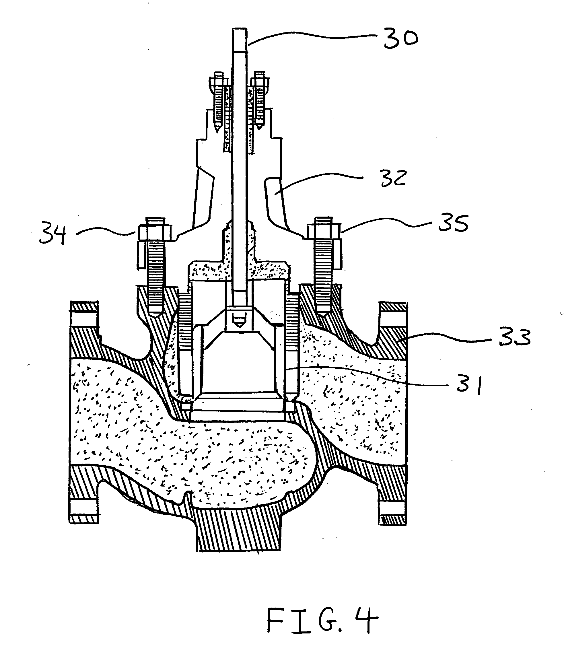
[0041]FIG. 4 shows a cross-sectional view of a conventional two-piece control valve.

[0042] As with the previously described valves, this valve has a stem 30 and a plug 31 that restricts the flow of materials through the flowline. The valve has an upper piece bonnet 32 and a lower piece body 33. Bolts 34 and 35 connect the upper bonnet and the lower body pieces of the valve. The use of this two-piece configuration requires many considerations before implementation of this valve design. Based on the environment in which a valve of this design will be implemented, it will necessary to know the pressure of the materials flowing through the line before incorporating a valve of this design.

[0043] The one-piece design of the present invention will eliminate many of the environmental conditions when deciding to use a valve of this design. Referring to FIG. 5, there is a cross-section side view of the one-piece valve design of the present invention in an initially closed valve. This valve ...


PUM


Abstract

The present invention provides an inline flow control valve for regulating the movement of materials through a flow line. The valve of the present invention has a design that provides external control of the inline plug instead of control based on flow pressure of the material flowing through the flow line. The valve of the present invention can comprise a one-piece housing design. This one-piece design can facilitate easier assembly and maintenance of the valve. The valve comprises a valve housing, a valve plug, guide member, and an actuation mechanism. This mechanism is a rack and pinion design comprising a shaft, a rotary pinion arm and a rack gear. The rack and pinion design converts circular motion from the shaft into linear motion of the valve plug in the flow line. The shaft, which an operator would use to control the motion of the valve plug, is not contained an integral valve bonnet.

Description

FIELD OF THE INVENTION [0001] This invention relates to a control valve apparatus for regulating the flow of materials (liquids and gases) through a flow line and in particular this invention relates to an inline flow control valve that uses a rack and pinion gearing mechanism to control the movement of a valve plug and thereby regulate the amount of material moving through a flowline. The invention further relates to an inline flow control valve that comprises a one-piece valve housing design to facilitate more efficient assembly and maintenance of the control valve. BACKGROUND OF THE INVENTION [0002] A valve is a mechanical device, which opens and closes in order to control the flow of materials, such as water, stream, oil, and gas chemicals, in flow lines such as pipes and vessels. Valves are used in a wide variety of familiar devices and many known tasks. For example, turning a dial on a gas stove varies the opening of a valve and regulates the flow of gas to the stove burner. T...

Claims


Application Information

Patent Timeline
Patent Type & Authority Applications(United States)
IPC IPC(8): F16K3/24F16K31/163F16K31/44F16K31/54
CPCF16K3/24F16K31/54F16K31/163
Inventor LAVERGNE, MORRIS JR.
Owner LAVERGNE JR MORRIS
Why Eureka
Try Eureka