Hybrid tandem compressor system with multiple evaporators and economizer circuit

a compressor system and evaporator technology, applied in the field of refrigerant cycle, can solve the problems of high cost, inability to meet the requirements of cooling at different levels, and inability to apply standard tandem compressor configuration,

Inactive Publication Date: 2007-06-12
CARRIER CORP
View PDF4 Cites 68 Cited by
  • Summary
  • Abstract
  • Description
  • Claims
  • Application Information

AI Technical Summary

Benefits of technology

[0008]In a disclosed embodiment of this invention, precise control of various sub-sections of an environment can be achieved by utilizing distinct evaporators for each of the separate areas. Each of the evaporators communicates with a separate compressor, while the compressors send compressed refrigerant through a common discharge manifold to a common condenser. Thus, there is no need in providing all of the components of two individual refrigerant circuits (such as an additional condenser and additional condenser fans). In this manner, a separate cooling control of each of the cooling temperature zones is achieved.

Problems solved by technology

However the cooling at different levels will not work with application of standard tandem compressor configuration, as it would require the application of a dedicated circuit for each cooling level.
This arrangement having a dedicated circuitry for each temperature level would be very expensive.

Method used


Image

  • Hybrid tandem compressor system with multiple evaporators and economizer circuit
  • Hybrid tandem compressor system with multiple evaporators and economizer circuit
  • Hybrid tandem compressor system with multiple evaporators and economizer circuit

Examples


Embodiment Construction

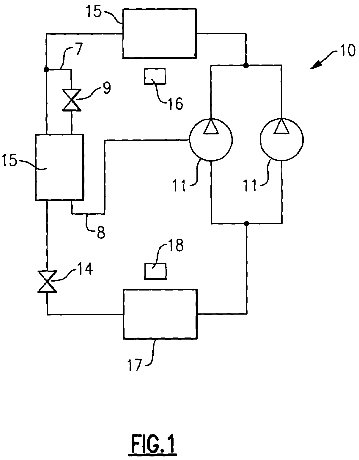
[0017]Referring to FIG. 1, earlier tandem compressor system 10 is shown to include two separate compressors 11, an evaporator 17, condenser 15, expansion device 14, condenser fan 16, evaporator fan 18 and associated piping. An economizer circuit includes an economizer heat exchanger 15 receiving a main refrigerant flow and a tapped refrigerant flow tapped from the main circuit into a refrigerant line 7. As known, the tapped refrigerant flow passes through an expansion device 9. Downstream of the economizer heat exchanger 15, the tapped flow is returned through a refrigerant line 8 to an intermediate compression point in at least one of the compressors 11. Such a system was disclosed in a prior U.S. patent application Ser. No. 10 / 769,161, filed 30 Jan. 2004 and entitled “Refrigerant Cycle With Tandem Economized and Conventional Compressors” and assigned to the assignee of the present invention. Obviously, more than two compressors can be utilized in the tandem configuration with more...


PUM


Abstract

A tandem compressor refrigerant cycle with an economizer circuit is introduced to provide additional capacity and improve system efficiency. In this system, tandem compressors deliver compressed refrigerant to a common discharge manifold, and then to a common condenser. From the common condenser, the refrigerant passes to a plurality of evaporators, with each of the evaporators being associated with a separate environment to be conditioned. Each of the evaporators is associated with one of the plurality of compressors. By utilizing the common condenser, and yet a plurality of evaporators, the ability to independently condition a number of environments is achieved without the requirement of the same plurality of separate complete refrigerant circuits for each of the environments. In some embodiments, several of the plurality of compressors can be provided by compressor banks having its own plurality of compressors. Some of the compressors in the compressor bank can have intermediate injection ports to accept refrigerant vapor from the economizer circuit. In particular, the economizer circuit provides additional capacity to the evaporators with relatively high load requirements.

Description

BACKGROUND OF THE INVENTION[0001]This application relates to a refrigerant cycle utilizing tandem compressors sharing a common condenser, but having separate evaporators, and wherein an economizer circuit is employed.[0002]Refrigerant cycles are utilized in applications to change the temperature and humidity or otherwise condition the environment. In a standard refrigerant system, a compressor delivers a compressed refrigerant to an outdoor heat exchanger, known as a condenser. From the condenser, the refrigerant passes through an expansion device, and then to an indoor heat exchanger, known as an evaporator. At the evaporator, moisture may be removed from the air, and the temperature of air blown over the evaporator coil is lowered. From the evaporator, the refrigerant returns to the compressor. Of course, basic refrigerant cycles are utilized in combination with many configuration variations and optional features. However, the above provides a brief understanding of the fundamenta...

Claims


Application Information

Patent Timeline
Patent Type & Authority Patents(United States)
IPC IPC(8): F25B1/10
CPCF25B5/00F25B5/02F25B41/043F25B2400/075F25B2400/13F25B2400/22
Inventor LIFSON, ALEXANDERTARAS, MICHAEL F.
Owner CARRIER CORP
Why Eureka
Try Eureka