Pedal reaction force device

a technology of reaction force and pedal device, which is applied in the direction of mechanical control device, process and machine control, instruments, etc., can solve the problems of difficulty in pedal device, pedal operation, driver, etc., and achieve excellent mounting efficiency

Active Publication Date: 2007-06-12
TOYODA IRON WORKS CO LTD
View PDF20 Cites 20 Cited by
  • Summary
  • Abstract
  • Description
  • Claims
  • Application Information

AI Technical Summary

Benefits of technology

[0009]The present invention was developed in view of the above-described situations, and it is therefore an object of the invention to provide a simple and inexpensive pedal reaction force device which is capable of easily setting reaction force characteristics close to conventional mechanical type pedal devices.
[0011]With a pedal reaction force device according to the first aspect of the invention, a pedaling reaction force is applied to an operating pedal on the basis of displacement by a reaction force generating unit which is mechanically displaced in accordance with a pedaling operation of the operating pedal, and simultaneously, a variation pattern of the displacement magnitude of the reaction force generating unit, that is, the characteristics (reaction force characteristics) for varying the pedaling reaction force are mechanically set by a displacement characteristics regulating mechanism. Therefore, a higher degree of freedom in setting the reaction force characteristics can be obtained in comparison with a case where the pedaling reaction force is non-linearly varied by using a number of spring members, and it is possible to easily apply reaction force characteristics close to those of a conventional mechanical type pedal device. However, a more excellent response can be obtained together with a more inexpensive structure in comparison with a case where reaction force characteristics are electrically varied by using a sensor or a drive device.
[0013]With the first preferred form of the pedal reaction force device according to the invention, a damper device for applying a pedaling reaction force to an operating pedal on the basis of circulation resistance of a fluid and a spring member for applying a pedaling reaction force to the operating pedal on the basis of resilient deformation are provided as a reaction force generating unit. Although the pedaling reaction force is mechanically applied by the damper device and spring member, the pedaling reaction force brought about by the damper device differs, depending on pedaling speeds, wherein a greater pedaling reaction force is mechanically applied in fast pedaling than in slow pedaling, and hysteresis in which a reaction force in a pedaling operation differs from that in a returning operation is mechanically applied. Therefore, it is possible to easily obtain reaction force characteristics close to a conventional mechanical type pedal device in different pedaling speeds or in a returning operation.
[0015]With the second referred form of the pedal reaction force device according to the invention, since the spring member is a coil spring substantially concentrically disposed at the outer circumferential side of the damper device so as to surround the damper device and is devised so as to be displaced in accordance with a prescribed variation pattern in an integrated manner with the damper device by a single displacement characteristics regulating mechanism, the device is further simplified and constructed to be further compact in comparison with a case where separate displacement characteristics regulating mechanisms are provided with respect to the damper device and spring member, wherein excellent mounting efficiency thereof in a vehicle can be obtained.

Problems solved by technology

In such an electric brake pedal device, since only a reaction force brought about by a return spring operates and almost no reaction force is produced, there was a problem in that it was difficult for a driver, who is accustomed to a conventional mechanical type pedal device, to carry out a pedaling operation.

Method used


Image

  • Pedal reaction force device
  • Pedal reaction force device
  • Pedal reaction force device

Examples


Embodiment Construction

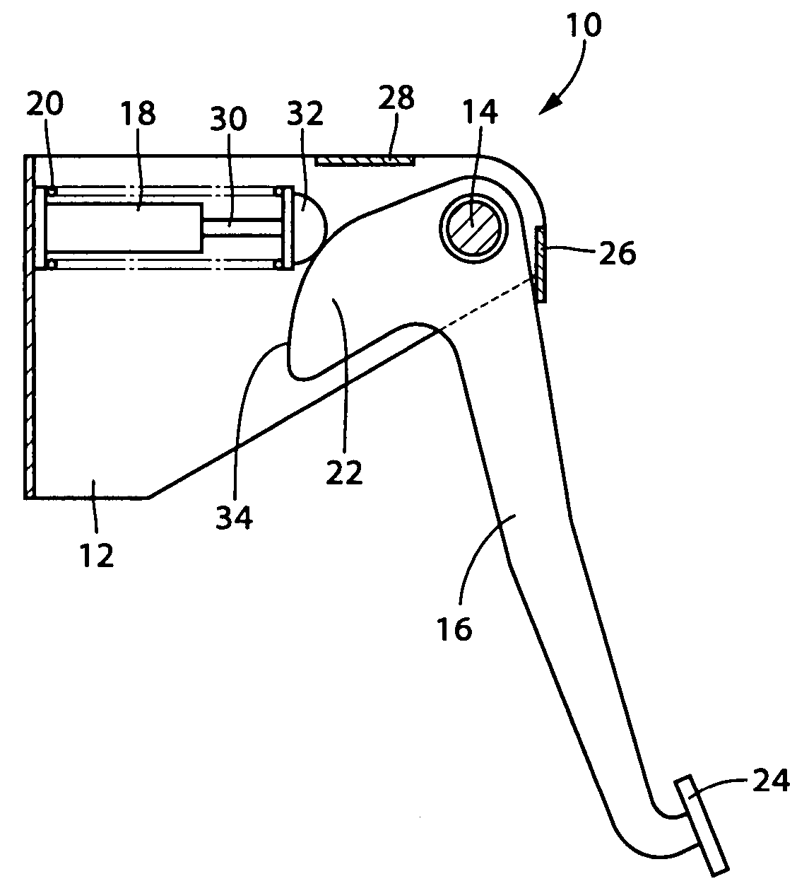
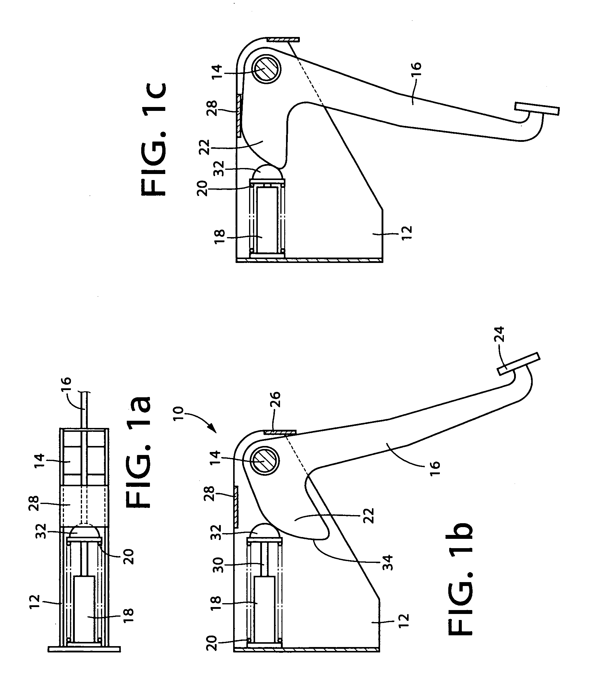
[0034]FIGS. 1a and 1b are views showing a pedal reaction force device 10 according to one embodiment of the invention. The pedal reaction force device 10 may be preferably used for, for example, an electric type normal brake pedal device for a vehicle. The pedal reaction force device 10 is provided with an operating pedal 16 pivotally disposed around the axial center of a substantially horizontal support shaft 14 secured on a bracket 12 fixed in an integrated manner with a vehicle body, a damper device 18 and a spring member 20, which operate as a reaction force generating unit, and a cam 22 acting as a displacement characteristics regulating mechanism. A depressible portion (pad) 24 is provided at the lower end part of the operating pedal 16, wherein the operating pedal 16 is turned clockwise around the support shaft 14 by a driver making a pedaling operation, and since a sensor (not illustrated) detects the pedaling stroke (a pivotal motion around the support shaft 14 and a displa...


PUM


Abstract

In a pedal reaction force device, a pedaling reaction force is applied to an operating pedal on the basis of a displacement magnitude and a variation speed of the displacement magnitude by a damper device and a spring member which are mechanically displaced in accordance with a pedaling operation of the operating pedal. The variation pattern of the displacement magnitude, that is, variation characteristics of the pedaling reaction force, are mechanically set by a cam.

Description

[0001]This application is based on Japanese Patent Application No. 2004-031565 filed Feb. 9, 2004, the contents of which are incorporated hereinto by reference.BACKGROUND OF THE INVENTION[0002]1. Field of the Invention[0003]The present invention relates to improvements of a pedal reaction force device that electrically detects a pedaling stroke of an operating pedal and applies a pedaling reaction force to an operating pedal for actuating a hydraulic brake, etc.[0004]2. Discussion of Related Art[0005]An electric pedal device which detects a pedaling stroke of an operating pedal and causes a hydraulic device or an electric motor to execute a prescribed operation has been proposed for a normal brake pedal device for a vehicle. In such an electric brake pedal device, since only a reaction force brought about by a return spring operates and almost no reaction force is produced, there was a problem in that it was difficult for a driver, who is accustomed to a conventional mechanical type...

Claims


Application Information

Patent Timeline
Patent Type & Authority Patents(United States)
IPC IPC(8): G05G1/30F16H53/00B60T7/06G05G5/05
CPCG05G1/30G05G5/05Y10T74/20528Y10T74/2107Y10T74/20888Y10T74/2101
Inventor FUJIWARA, NOBORU
Owner TOYODA IRON WORKS CO LTD
Why Eureka
Try Eureka